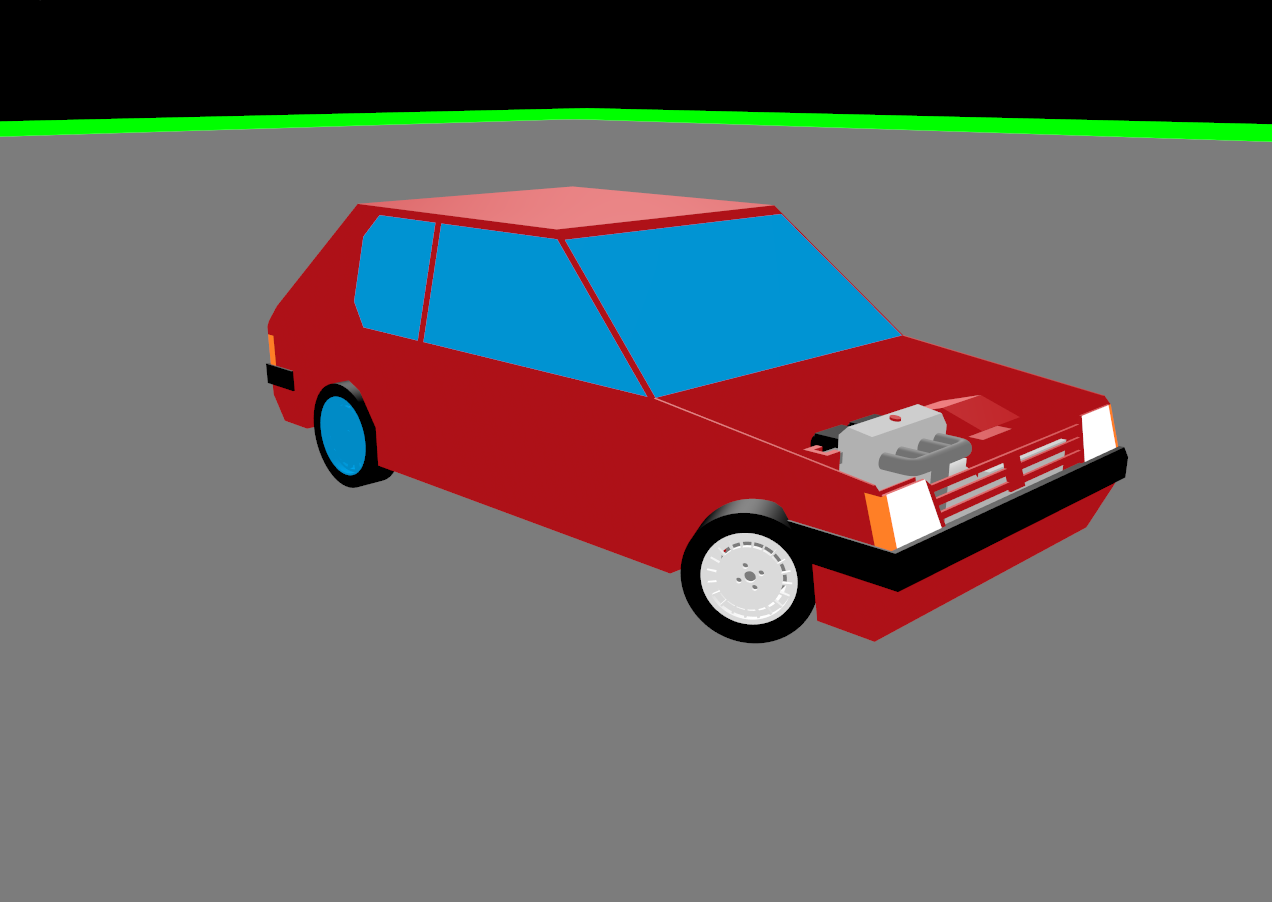
Some playing with the wheels 
4 Likes
Well actually I use Blender as Level Editor currently 
It is no long-term Solution and I have some ideas in my head for some DSL and descriptive maps, but currently I only use Blender.
For this I make heavy use of userData or Properties in Blender. That way I mark planes which should become water and such things.
I think that Blender is also an awesome base for this, but I have no clue how I could combine those. Maybe using xbuf to render into Blender and stuff?
Because building a custom level editor also takes it’s time
1 Like
I didn’t want to make a level editor, I thought it would be a waste of time and something I would yet again over engineered, spend countless hours reinventing the wheel, and only wanted to make because it sounded fun.
Initially I was using Photoshop as my level editor and png files as the save format, worked great, did the job, but was very fiddly and hard to use. So I though “I will throw one day at an editor and see where it gets me”… I would say it was well worth the risk, and if it all went tits up, I would have only lost a day.
As @rickard wisely noted, this editor is for this specific game only, it is not intended to be a generic editor. Given how quickly it all came together, in future I will not be afraid of adding a quick custom level editor to a project .
NB. This is applicable to me since I have a bit of jME experience and it was relatively quick to build for me, speaking from experience: for a lot of the newer monkeys out there, DON"T WASTE TOO MUCH TIME BUILDING TOOLS FOR YOUR GAME! otherwise before you realise it, you have a suite of tools wrapped around a broken unfinshed ‘game’. A working game with one level is infinately better than having a broken game with 100 levels 
For those who just want something quick, you can get pretty far with this approach:
Perhaps less fiddly than photoshop and can potentially hold more meta-data.
1 Like
HA! I read that article and did exactly that for Spoxel. I have a number of structures, holes, and ores that get placed in the world based on data loaded from a bunch of csv files. It may not be very nice visually but it is pretty fast to edit and move things around.
I love Blender, and went as far as to try and add my own UI components in blender with python. My experience of python and blender was a nightmare, so end up just exporting text. Also ended up making a sort of level editor in JME… just placing stuff and telling what bit should run what code and so on.
For Hostile Sector, I went for a text based format. So at first I just sat with Notepad, dotting numbers in a grid based on the terrain type (and later on, height). I then had a list of objects in the map, with type, tile coordinates and rotation also in the text file. Vegetation wasn’t “objects” as such or it would have become too much. They were just plotted based on the terrain type. Eventually I made a level editor in-engine where I could change terrain and add/remove objects. Technically, I couldn’t create new maps with it. I had to create a template first by copying a previous map and then edit it.
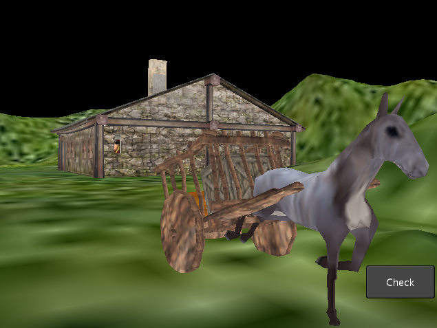

Here’s a before and after for my scene. The first is a screenshot from Android. The second image I put into my picture taking add on and put in some filters and lighting.
This is a good example of how different the exact same scene can look between Android and PC, and the major differences some lights and filters can make.
6 Likes
This is a good example of how different the exact same scene can look between Android and PC
Yeah, some things appear much closer in the Android image ![]()
The first picture was mid animation. The second one is just the still scene. I figured it got the point across.
Here’s a short video of my latest work: volumetric lighting 
I still need to make some kind of temporal filtering to remove the blockiness though.
17 Likes
Looks great! How have you distributed your samples ? You could probably alleviate that banding with a more sophisticated sampling method (something that has peaked my interest lately).
1 Like

Took about an hour of screwing around with 2 jme Spheres and 6 jme Cylinders, it is for nothing, a Box would have have worked just as fine, we all waste time for no reason, leave me alone.


13 Likes
The sampling is achieved with a low resolution TextureArray, like 160x90x128 (128 slices in the z direction). I can get rid of the banding by reducing the gap between the z slices when close to the camera.
However, I still need to smooth the xy-sampling to get rid of the blocky appearance. Any ideas?
1 Like
how are you up-scaling it at the moment?
Well, you could say, that there is no special upscaling at the moment.
What I do is this: Each slice holds the volumetric lighting information (color) and opacity (or alpha value) from the camera, up to that slice. In a Filter, I pick the proper slice based on the depth value of the rendered scene and blend that pixel accordingly.

Took this depth only ssao filter I found online and made it glsl in jme. Still has to be blurred and so on. Not as nice as the other one I think, but no normal pass required.
10 Likes
Working on adding joints to my physics engine (constraints)… I have fixed ball joints and hinge joints sort of working. I added a visualization of them to start working on the object-to-object joints. You can see some balls hanging in this picture:

…and two on the floor doing a good job of being a bad example. (Bad examples are good for showing the joint view.)
Green ball + line is the ‘attachment’ point on body1. Blue ball + line is the ‘attachment’ point on body2. The red ball and lines show the error where the joint hasn’t properly resolved itself. (No surprise here, really.)
For the hanging balls, we see a ‘hinge joint’ in the background and then a couple ball joints… two with offset attachment points like the object-to-object example.
The floating text is just labels I can arbitrarily add to the sim and in this case it used to tell me what the different damping was for the joints when I was testing damping. Now it indicates hinge versus ball but still shows the damping value.
7 Likes
You just didn’t want to stop…
8 Likes
I am curious. I want to do the same thing. Can you give me some instruction about how to accomplish it?