I am developing a lathe simulator and I am faced with the problem of changing the shape of the part when interacting with the cutter.
Maybe you can somehow change the location of the triangles relative to the cutter.
If someone came across a similar, I will be glad to help.
Sorry for english)
1 Like
Sure. You get the vertices of the mesh and change their positions, then update the mesh with the new vertices.
BufferUtils.getVector3Array(geom.getMesh().getFloatBuffer(VertexBuffer.Type.Position));
I watch a lot of stuff like this on the internet, so I have a vague idea of lathes, but ideally you’d want to create a “cut” of vertices parallel to both sides of the blade and the position of those vertices closer to the center.
That’s not simple enough in my head to go over in a single post. We can help if you make a start and get stuck.
i always wanted to do something like this, skipping multiple models for cutted part that would save a lot of time.
but i had some problems, so i skipped trying.
Thank you very much, you helped me change the mesh. But I still have an unsolved problem, I need to find out which of the points to change position in a collision with a cutter. But using CollisionResult, I can only get the coordinates of the triangle. If the appropriate method to solve this issue?
The coordinates will be the same as one of the coordinates in the mesh. Just iterate them until one equals the other. It won’t be the same object, it will just have the same values, so .equals and not == them to compare.
Unless you move the lathe you will also hit the same group of vertices, so you may as well store the indexes somewhere to avoid continually iterating over a larger group.
Often you’d use a data structure like Half-Edge for such mesh manipulation because it allows access to the neighbourhood of Vertices/Edges/Faces without large iterations.
But since the mesh will have axial symmetry, could it be easier if you only change a 2D representation of the outline and then recreate the mesh by rotating the outline around the axis?
1 Like
In general, I obtained the coordinates of the points using triangle.get (i) and compared them using vector [i] .equals. Then, I set the coordinates of the most extreme point of the cutter to vector [i].
billet.getMesh().clearBuffer(VertexBuffer.Type.Position);
billet.getMesh().setBuffer(VertexBuffer.Type.Position,3, BufferUtils.createFloatBuffer(vector));
billet.updateModelBound();
billet.setMesh(billet.getMesh());
But there were problems, after changing the coordinates of the points of my mesh, all the changed points began to take the cutter position even if I take it away within the mesh itself.
This means that collisions occur even if I impose in places where the mesh no longer exists.
Why it happens?
Can you post the code that does this? Where it detects the collision and modifies the mesh.
WARNING: I’m a stupid student!
Before that, I tried to calculate the distance to the nearest point and change the position only for it. But for clarity, back to the original method. Because the previous method contributed to neoco-corrective grid correction.
> CollisionResults results = new CollisionResults();
> billet.collideWith(cutterHead.getWorldBound(), results);
> if (results.size() > 0) {
>     for (int i = 0; i < results.size(); i++) {
>         CollisionResult collisionResult = results.getCollision(i);
>         Triangle triangle = new Triangle();
>         collisionResult.getTriangle(triangle);
>
>         Vector3f[] vector = BufferUtils.getVector3Array(billet.getMesh().getFloatBuffer(VertexBuffer.Type.Position));
>         for (int j = 0; j < vector.length; j++) {
>             for (int k = 0; k < 3; k++) {
>                 if (vector[j].equals(triangle.get(k))) {
>                     vector[j].set(cutterHead.getWorldTranslation());
>                 }
>             }
>         }
>
>         billet.getMesh().clearBuffer(VertexBuffer.Type.Position);
>         billet.getMesh().setBuffer(VertexBuffer.Type.Position, 3, BufferUtils.createFloatBuffer(vector));
>         billet.updateModelBound();
>         billet.setMesh(billet.getMesh());
>     }
> }
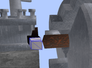
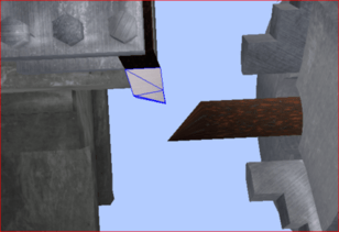
The item is half cut:
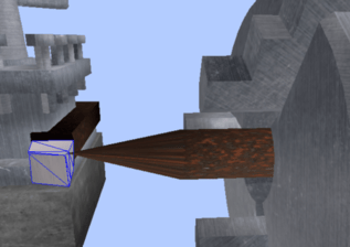
When took the cutter from the processed detail:
When you move the vertex point it will still be in the bounding box of your blade - right at the edge - and so will still collide. Add a small distance to the “new” position so that it is outside the blade bounding box.
I said that when I take the cutter out of the billet, the modified points take the last position of the cutter exit from the past coordinates of the mesh.
I can certainly try to move by 0.001. But I do not think that will help.
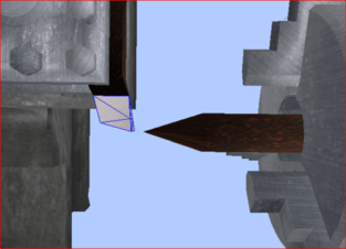
Brought out of the original mesh:
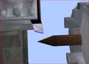
Now I have brought the cutter to the old mesh boundaries:
I’m sorry, I’ve read your response over and over and I just don’t understand what you are saying. Maybe it’s just me.
As much as I like the talk about toying with mesh geometry like this, have you tried any other solutions that might be easier? I’m not sure how this would look, but what if you just put a large number of very flat cylinders all in a row? Maybe, 500 or so?
That should make altering things far easier; no need to worry about exactly where a collision happened. Whenever the blade collides with one of the cylinders, just shrink that cylinder’s radius a bit. And I emphasize a bit–in real life a lathe isn’t going to let you cut say half way into the wood instantly, you need to go slower. So a small set shrinkage amount should be all you need–no need to calculate how far deep inside the blade is. (Of course, you’d need to make sure it doesn’t penetrate too far, to keep it realistic.)
You may not get super realistic results like this (lathe speed won’t really be a thing) but that should simplify things greatly if you can get it to look decent. You might need to mess with texture coordinates a bit if you want to make the long stem of cylinders resemble a true wood-like pattern.
If you really wanted to get fancy, you could taper the cylinders (cut off cones really) to match the size of the adjacent ones… but start simple first.
2 Likes
I dont know if it would be simpler, but this could be a good case for volumetric rendering of a scalar density field (or signed distance field). This way, the underlying scalar field could be modified in a Constructive Solid Geometry way, and even a 3d texture could be used and revealed as the lathe cuts.
…but for a lathe-specific use case, i would have to agree with @1000ml that this could likely be more easily accomplished by modifying a 2d curve which is rotated around the axis of the lathe rotation when rendered.
Ok, thanks, I’ll try to make it easier.
But I do not know how to do it. I would not mind if you gave a link to a good source on this topic so that I could study it.
I solved the problems by adding the createCollisionData () method;
I apologize for my English) and thanks for the help