[SOLVED]Math problem: change axis from 3ds max to jME3

Hi, all.
I’m now learning skeleton animation and trying developing a plugin to import old 3dmax ASE model. Now I have problem with the bones.

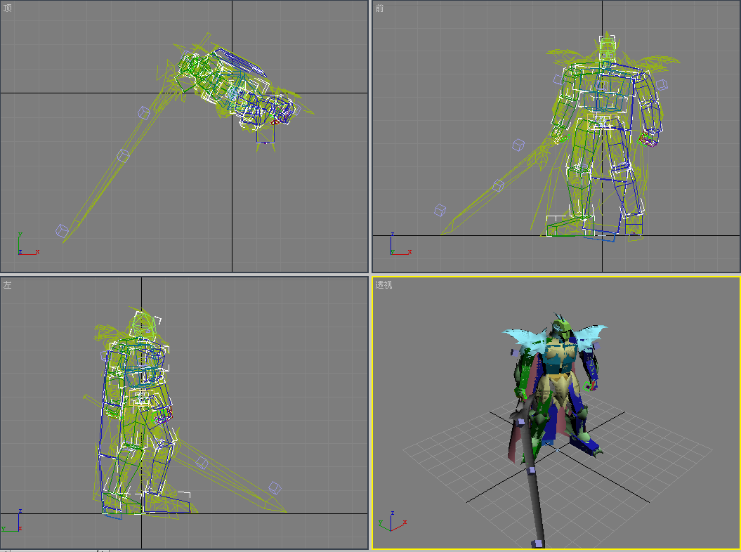
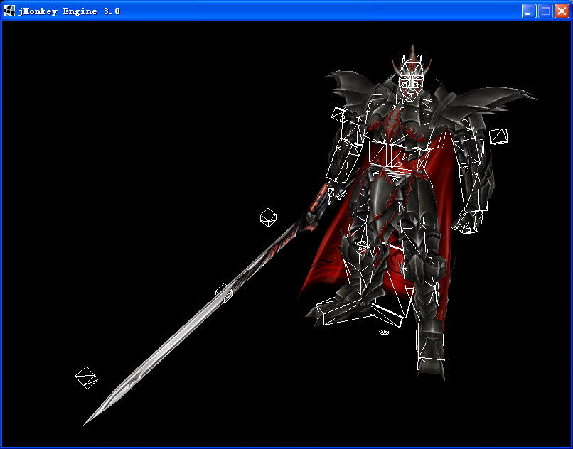
As i learned so far, each bone in fact is a POINT with location, rotation and scale. But, when I see the ASE models in 3dmax, the bone looks like a Geometry.

I can import the model into jme3 with my AsePlugin, it looks like this:

And this is the bone:

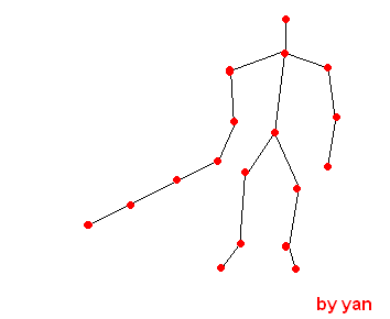
I don’t think that is what i learned so far. In my brain it should be look like this:

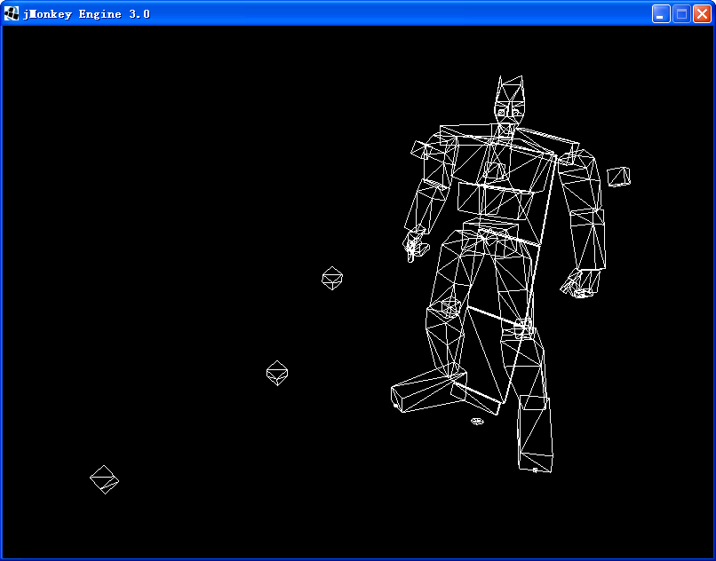
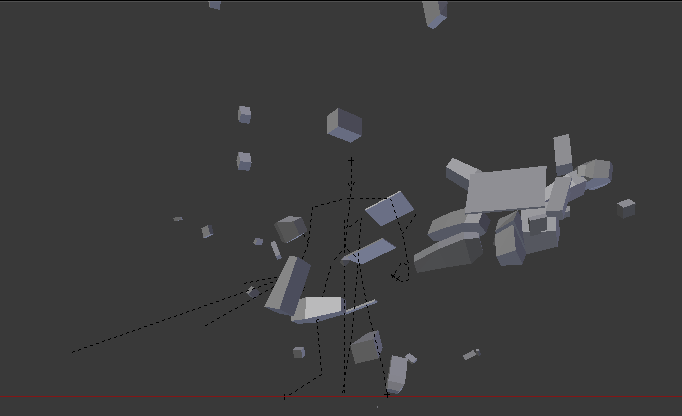
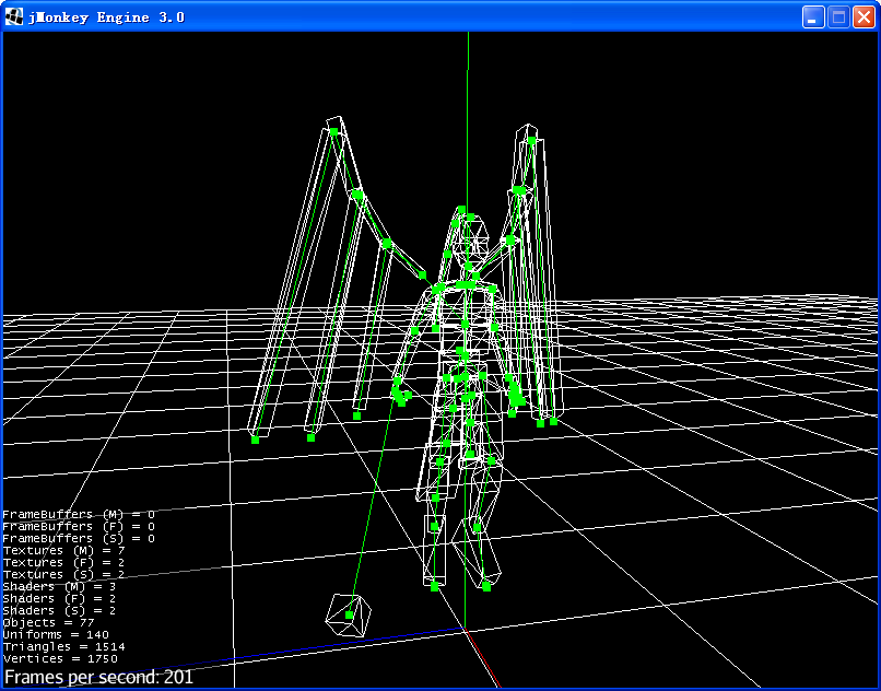
I think maybe 3dmax was wrong. So I tried to use blender. Since I didn’t find how to import ASE model in blender, I export the ASE model to *.3DS with 3dmax and import it to blender. Now the bone looks like this(I deleted the skin):

OK, I can see the “Bones” now. I think this is what I need( just forget the flying bones…). I think it’s possible to calculate the bone position with data in the ASE model, as blender do. But infomation about ASE animation is so rare, would you please recommend me some website or pages to learn about it? Or maybe some info about how blender do it?

Thank you.

In my ASE models i see every GeomObject has a part called *NODE_TM, I think its the key data to calculate bone position, rotation, scale. But I have tried many times and failed because I don’t really understand this part.

Following are two bones in death_knight model: “Bip01” and “Bip01 Footsteeps”

*GEOMOBJECT {
*NODE_NAME “Bip01”
*NODE_TM {
*NODE_NAME “Bip01”
*INHERIT_POS 0 0 0
*INHERIT_ROT 0 0 0
*INHERIT_SCL 1 1 1
*TM_ROW0 -0.4326 -0.9016 0.0021
*TM_ROW1 0.9016 -0.4326 0.0026
*TM_ROW2 -0.0015 0.0030 1.0000
*TM_ROW3 -0.0031 -0.0242 49.4540
*TM_POS -0.0031 -0.0242 49.4540
*TM_ROTAXIS 0.0002 0.0020 1.0000
*TM_ROTANGLE 2.0182
*TM_SCALE 1.0000 1.0000 1.0000
*TM_SCALEAXIS 0.0000 -0.0007 -1.0000
*TM_SCALEAXISANG 0.1811
}
}

*GEOMOBJECT {
*NODE_NAME “Bip01 Footsteps”
*NODE_PARENT “Bip01”
*NODE_TM {
*NODE_NAME “Bip01 Footsteps”
*INHERIT_POS 1 1 1
*INHERIT_ROT 1 1 1
*INHERIT_SCL 1 1 1
*TM_ROW0 1.0000 0.0000 0.0000
*TM_ROW1 0.0000 1.0000 0.0000
*TM_ROW2 0.0000 0.0000 1.0000
*TM_ROW3 -0.0031 -0.0242 0.0017
*TM_POS -0.1037 -0.1306 -49.4520
*TM_ROTAXIS -0.0002 -0.0020 -1.0000
*TM_ROTANGLE 2.0182
*TM_SCALE 1.0000 1.0000 1.0000
*TM_SCALEAXIS 0.0000 0.0000 0.0000
*TM_SCALEAXISANG 0.0000
}
}

In blender its possible to add custom geometry for each bone - maybe here is the same.

Hi, all.
I guess NODE_NAME, NODE_PARENT, TM_POS, TM_ROTAXIS, TM_ROTANGLE, TM_SCALE is what i need to make a jME3 bone. so I made it like this:

@see AseProcessor compileSkeleton()

The skeleton looks pretty good but something wrong with the axis.


As far as i know, 3ds max axis is different with jME3 axis.

/*
 * 3D MAX Axis:
 *                 z     x
 *                 |    /
 *                 |   /
 *                 |  /
 *                 | /
 *                 |/
 *     y ----------*
 * JME3 Axis:
 *          | y
 *          |
 *          |
 *          |
 *          |
 *          *---------- x
 *         /
 *        /
 *       /
 *    z /
 * 
 */

I tried to modify obj.pos by changing Vector3f(x, y, z) to Vector3f(-y, z, -x), then it look like this:

I need your help with math problem…I’m really not good at it. How can I make the skeleton right?

Problem solved.
Each bone has 3 attributes: Translation, Rotation and Scale. I forget the other two. Now I do it in this way:

        // Translation
        Vector3f position = new Vector3f(-obj.pos.y, obj.pos.z, -obj.pos.x);
        
        // Rotation
        Quaternion rotation = new Quaternion();
        Vector3f rotAxis = new Vector3f(-obj.rotAxis.y, obj.rotAxis.z, -obj.rotAxis.x);
        rotation.fromAngleAxis(-obj.rotAngle, rotAxis);
        
        // Scale
        Vector3f scale = new Vector3f(obj.scale.y, obj.scale.z, obj.scale.x);
        
        bone.setBindTransforms(position, rotation, scale);

How pretty skeletons, I like it.

After that I will handle with animations…TranslationTrack, RotationTrack, ScaleTrack maybe have the same problem.

1 Like