The settings says zero on location and rotation, no matter what part I selected.
Isn’t it better to move all the parts to a invidual layer and place them so each hole is in location 0,0,0?
Like this.
Place the layers like this:
I will try an not confuse you with this.
Each objects origin will determine where it rotates from. Appling the L, R, S, just zeros these things out. Otherwise when jme moves the object, it would be offset and weird things happen.
If the origin is in the middle of the object and you attach it to a node then it will be centered in the node, assuming you have applied everything.
If the origin is at the center of the pivot point for that object and you add it to the node then it will rotate the way you want it to, as long as you have applied everything.
To simplify, if you have an object with its origin centered and you place it in the scene at 0,0,0, it will sink into the floor half way, assuming you have applied everything.
You will need to offset each node at the start to account for the pivot point location. As everyone else has said, the node parenting will do all the work for you, you will only need to manipulate whatever node you want to get the movement you’re after.
You rotate the base and all children will follow. You rotate arm one and arm two and the claw will follow. You rotate arm two and the claw will follow, etc.
Edit: To keep things simple, make your pivot points at easily known numbers like one meter, two meters or 3.5 meters, etc. You don’t have to but it will be easier for you.
Edit: To keep things even more simple, make all node/pivots align along the Y axis in jme first and then rotate into the starting position after initialization is complete.
I think I will try and clear this up for you as much as possible.
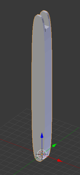
For clarity, I will say you have these five separate objects in blender, all parts are properly positioned vertically along the Z axis.
- Base
- Arm 1
- Arm 2
- Arm 3
- Claw
There is no angle in the arm or claw as you show in the above post. This is a basic principle of modeling objects like this where humanoids are posed in a T or A position and objects like this with the most minimal amount of deviation as possible.
- Set the
Baseorigin at the bottom center and apply L, R, S. - Select the base and In edit mode select all parts of the hole, both sides, and snap cursor to selected.
- In object mode, make a note of the cursor Z translation, select
Arm 1, set origin to cursor and apply L, R, S. - Select
Arm 1and In edit mode select all parts of the hole, both sides, thatArm 2pivots from and snap cursor to selected. - In object mode, make a note of the cursor Z translation, select
Arm 2, set origin to cursor and apply L, R, S. - Repeat these steps for the remaining parts.
When done, select one part at a time and export obj, remembering to check the Selection Only checkbox and any other settings you deem necessary.
You now have all your pieces ready to assemble.
- Add each part to a node, starting with the base, setting its translation to 0,0,0.
- Create a node for each of the remaining parts, setting each nodes Y translation with the Z translation you noted down before.
- Attach the Claw node to the Arm 3 node, the Arm 3 node to Arm 2 node, Arm 2 node to Arm 1 node, Arm 1 node to base node.
You can now play around with Quanternions.
Hi!
It didn’t work out for me. At least, I could place the parts at right place. But rotating them would cause that everything rotates at 0,0,0.
I will try to move the orgin of each part. I hope.
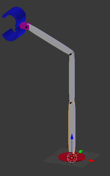
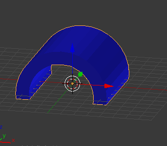
Edit: can I move the orgin of the nodes so when I rotate an object, it will rotate around the orgin? I want to set the masscenter orgin of the half circles to rotate around the 4th Bolt (upper top).
// Load the parts
        Spatial plate = assetManager.loadModel("Models/Plate.j3o");
        Spatial halfCircle1 = assetManager.loadModel("Models/HalfCircle1.j3o");
        Spatial halfCircle2 = assetManager.loadModel("Models/HalfCircle2.j3o");
        Spatial bolt1 = assetManager.loadModel("Models/Bolt1.j3o");
        Spatial bolt2 = assetManager.loadModel("Models/Bolt2.j3o");
        Spatial bolt3 = assetManager.loadModel("Models/Bolt3.j3o");
        Spatial bolt4 = assetManager.loadModel("Models/Bolt4.j3o");
        Spatial block = assetManager.loadModel("Models/Block.j3o");
        Spatial arm1 = assetManager.loadModel("Models/Arm1.j3o");
        Spatial arm2 = assetManager.loadModel("Models/Arm2.j3o");
        Spatial arm3 = assetManager.loadModel("Models/Arm3.j3o");

        // Create the nodes
        Node plateNode = new Node();
        Node arm1Node = new Node();
        Node arm2Node = new Node();
        Node arm3Node = new Node();
        Node blockNode = new Node();
        Node bolt1Node = new Node();
        Node bolt2Node = new Node();
        Node bolt3Node = new Node();
        Node bolt4Node = new Node();

        // Root
        rootNode.attachChild(plateNode);
        plateNode.attachChild(plate);

        // Plate
        plateNode.attachChild(bolt1);
        plateNode.attachChild(bolt1Node);

        // Bolt1
        bolt1Node.attachChild(arm1);
        bolt1Node.attachChild(arm1Node);


        // Arm1
        arm1Node.attachChild(bolt2);
        arm1Node.attachChild(bolt2Node);

        // Bolt2
        bolt2Node.attachChild(arm2);
        bolt2Node.attachChild(arm2Node);

        // Arm2
        arm2Node.attachChild(bolt3);
        arm2Node.attachChild(bolt3Node);

        // Bolt3
        bolt3Node.attachChild(arm3);
        bolt3Node.attachChild(arm3Node);

        // Arm3
        arm3Node.attachChild(bolt4);
        arm3Node.attachChild(bolt4Node);

        // Bolt4
        bolt4Node.attachChild(block);
        bolt4Node.attachChild(blockNode);

        // Block
        blockNode.attachChild(halfCircle1);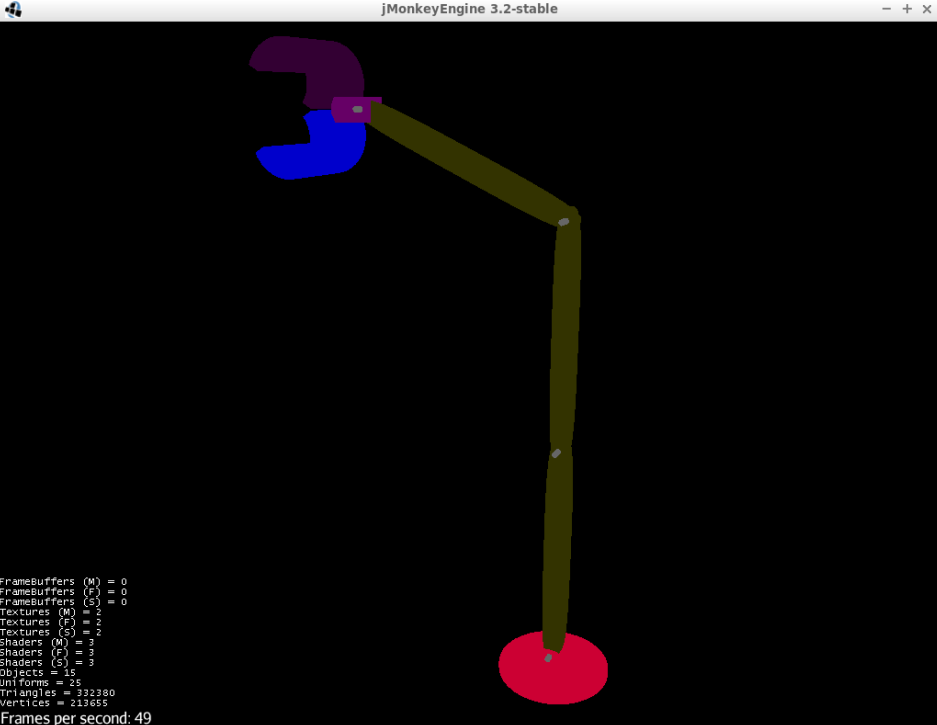
blockNode.attachChild(halfCircle2);Here is a fully working demonstration of what you want.
Controls:
WASD + AZ = move.
LMB = rotate camera.
MouseButton2 = rotate arm. (could be right mouse button, could be middle)
Grab an arm using MouseButton2, move the mouse up or down to rotate that arm. The arm will rotate on the Z axis.

package com.jayfella;

import com.jme3.app.SimpleApplication;
import com.jme3.input.event.MouseButtonEvent;
import com.jme3.input.event.MouseMotionEvent;
import com.jme3.material.Material;
import com.jme3.math.ColorRGBA;
import com.jme3.math.FastMath;
import com.jme3.math.Quaternion;
import com.jme3.math.Vector3f;
import com.jme3.scene.Geometry;
import com.jme3.scene.Node;
import com.jme3.scene.Spatial;
import com.jme3.scene.shape.Box;
import com.jme3.system.AppSettings;
import com.simsilica.lemur.GuiGlobals;
import com.simsilica.lemur.event.MouseEventControl;
import com.simsilica.lemur.event.MouseListener;

public class TestGrabber extends SimpleApplication {

    public static void main(String... args) {

        TestGrabber testGrabber = new TestGrabber();

        AppSettings appSettings = new AppSettings(true);
        appSettings.setResolution(1280, 720);

        testGrabber.setSettings(appSettings);
        testGrabber.setShowSettings(false);

        testGrabber.start();

    }

    TestGrabber() {
        super();
    }

    @Override
    public void simpleInitApp() {

        Material unshaded = new Material(assetManager, "Common/MatDefs/Misc/Unshaded.j3md");

        Box baseMesh = new Box(2,2,2);
        Geometry baseGeom = new Geometry("Base", baseMesh);

        Box armMesh_1 = new Box(1,5,1);
        Geometry arm_1 = new Geometry("Arm 1 Geometry", armMesh_1);
        Geometry arm_2 = new Geometry("Arm 2 Geometry", armMesh_1.clone());
        Geometry arm_3 = new Geometry("Arm 3 Geometry", armMesh_1.clone());

        arm_1.setLocalTranslation(0, 5f, 0);
        arm_2.setLocalTranslation(0, 5f, 0);
        arm_3.setLocalTranslation(0, 5f, 0);

        Material baseMaterial = unshaded.clone();
        baseMaterial.setColor("Color", ColorRGBA.White);
        baseGeom.setMaterial(baseMaterial);

        Material arm_1_material = unshaded.clone();
        arm_1_material.setColor("Color", ColorRGBA.Red);
        arm_1.setMaterial(arm_1_material);

        Material arm_2_material = unshaded.clone();
        arm_2_material.setColor("Color", ColorRGBA.Green);
        arm_2.setMaterial(arm_2_material);

        Material arm_3_material = unshaded.clone();
        arm_3_material.setColor("Color", ColorRGBA.Blue);
        arm_3.setMaterial(arm_3_material);


        Node baseNode = new Node("Base");
        baseNode.attachChild(baseGeom);

        Node arm_1_node = new Node("Arm 1 Node");
        arm_1_node.setLocalTranslation(0, 2f, 0);
        arm_1_node.attachChild(arm_1);

        Node arm_2_node = new Node("Arm 2 Node");
        arm_2_node.setLocalTranslation(0, 10f, 0);
        arm_2_node.attachChild(arm_2);

        Node arm_3_node = new Node("Arm 3 Node");
        arm_3_node.setLocalTranslation(0, 10f, 0);
        arm_3_node.attachChild(arm_3);

        baseNode.attachChild(arm_1_node);
        arm_1_node.attachChild(arm_2_node);
        arm_2_node.attachChild(arm_3_node);

        rootNode.attachChild(baseNode);


        GuiGlobals.initialize(this);

        ArmGrabber armGrabber = new ArmGrabber();

        MouseEventControl.addListenersToSpatial(arm_1_node, armGrabber);
        MouseEventControl.addListenersToSpatial(arm_2_node, armGrabber);
        MouseEventControl.addListenersToSpatial(arm_3_node, armGrabber);

        // camera stuff
        cam.setLocation(new Vector3f(0, 0, -50));
        cam.lookAt(baseNode.getLocalTranslation(), Vector3f.UNIT_Y);
        flyCam.setMoveSpeed(50);
        flyCam.setDragToRotate(true);

    }

    private float tpf;

    @Override
    public void simpleUpdate(float tpf) {
        this.tpf = tpf;
    }

    private class ArmGrabber implements MouseListener {

        private boolean grabbing;
        private int y;
        private int change;

        private final float one_degree = 0.0174533f;

        @Override
        public void mouseButtonEvent(MouseButtonEvent event, Spatial target, Spatial capture) {
            this.grabbing = event.isPressed() && event.getButtonIndex() == 2;
            y = event.getY();
        }

        @Override
        public void mouseEntered(MouseMotionEvent event, Spatial target, Spatial capture) {

        }

        @Override
        public void mouseExited(MouseMotionEvent event, Spatial target, Spatial capture) {

        }

        @Override
        public void mouseMoved(MouseMotionEvent event, Spatial target, Spatial capture ) {

            if (grabbing) {

                change = event.getY() - y;

                float angles[] = new float[3];

                Node grabbedArm = (Node) target;
                grabbedArm.getLocalRotation().toAngles(angles);

                angles[2] += change * tpf;

                if (angles[2] > FastMath.TWO_PI) {
                    angles[2] -= FastMath.TWO_PI;
                }

                if (angles[2] < -FastMath.TWO_PI) {
                    angles[2] += FastMath.TWO_PI;
                }


                grabbedArm.setLocalRotation(new Quaternion().fromAngles(angles));

            }

        }

    }

}
Hi!
Thank you for the quality code, but I still struggle to sett the rotational points. I understand you code you have written and I have been doing example like this before.
My issue is that if I rotate the bolt number 4, which is the absolute top bolt at the crane. I want the pink block and the two blue half circles to rotate to, around the bolt number 4. But it dosen’t because I have set the rotational point at wrong place. Other wise, the nodes works perfect.

I know what’s the problem is. I need to set the rotational point. To do that, I need to move all the parts in a individual layer and place them all at 0,0,0.
But @mitm told me that I should not do that. I should place the parts as they are right now, then place their center point at 0,0,0.
I think maybe since now you have working code, rather than listen to us, you should maybe try to understand the concept of what is happening and why it is happening. If one of us may be wrong, c’est la vie. It is all with good intention. But I think now the problem is your understanding.
I linked to the scenegraph tutorial, which is also in the header links above. Maybe try going through that again to “see” yourself where you are going wrong.
I really appreciate for your support and it have help me a lot. I need now to use that code you gave me, and I’ll try it and reflect how the theory works.
I give you a reply later how the result will be.
Thanks.
1 Like
Hi!
As I promise, I solve my problem now. I still need to practice on the coordinates and angles. Is there a way to display a xyz axis on the screen?

I solve this problem by sett all the parts in individual layers and place all the mass center of all parts at 0,0,0.
Loads of ways. My favourite is Lemur, written by @pspeed - here’s the website.
http://jmonkeyengine-contributions.github.io/Lemur/
// im sure you can deduce a maven dependency, I use gradle.
implementation "com.simsilica:lemur:1.10.0"
// initialize lemur...
GuiGlobals.initialize(this);
BaseStyles.loadGlassStyle();
GuiGlobals.getInstance().getStyles().setDefaultStyle("glass");

// make some stuff.
Label label = new Label("I am a label"):
Label.setLocalTranslation(20, camera.getHeight() - 20, 1); // set it to the top-left of the screen.
guiNode.attachChild(label);
The gui node is a a two dimensional scenegraph, and operates like windows or linux in that the X and Y coordinates define the pixel and the Z plane defines the Z order (like windows in your operating system) which look like pieces of paper on top of another.
so a vector3f of (100, 200, 3) would put the item 100 pixels across, 200 pixels up, with an order priority of 3. setting the Z index higher puts that item above the items with a lower order, and vice versa.
I should also note that you can put these labels and all other Lemur controls in the 3D scenegraph, too. If you want to make them always face the camera, just add a billboard control to it.
myLabel.addControl(new BillboardControl());
1 Like
Does not JME have a standard tool for this? Like a parameter to enable at main()?
I’m not a game developer, I’m an control engineer. I like to use JME to display and simulate approximation of mechanical systems because JME do the job really fast compared to OpenGL. So, Lemur might be a tool for RPG/FPS games.
Thanks for the information.
I’m not sure what you are looking for… But if you just need the coordinate arrows etc. then https://wiki.jmonkeyengine.org/jme3/advanced/debugging.html
Thank you. Just what I looking for. The axis works great!