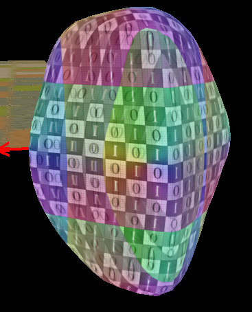
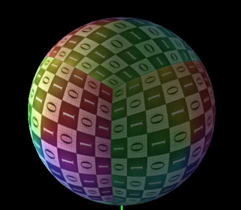
I’m currently working on a Rock generator based on GitHub - Erkaman/gl-rock: Procedural Generation of Rocks in WebGL work. The rock generation was pretty simple and it works like a charm. But I’m facing a problem after the rock transformation. The rock generation process is based on a normalized sphere which give me this mesh.
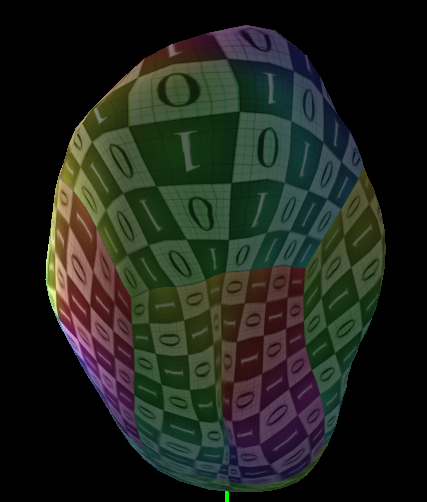
At this point the texture coordinate of the mesh are pretty and doesn’t need any processing. After the deformation process the uv are totally deformed and doesn’t fit the model correctly.
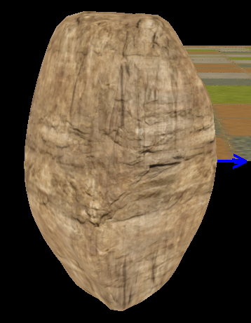
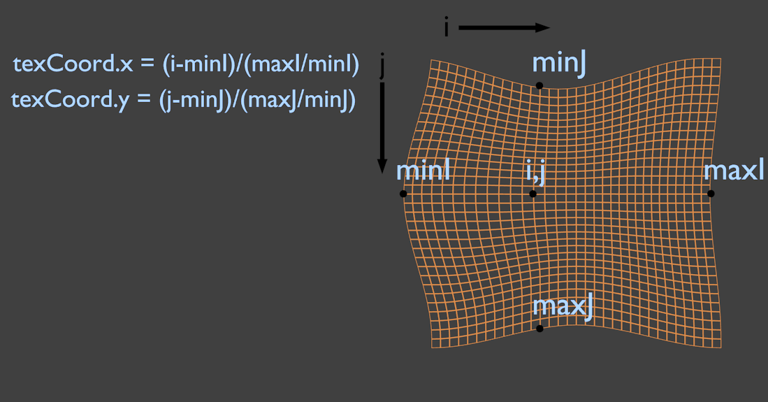
I managed to make an uv generation based on the deformation. I take each face separately and give them a proportion of the texture based on the normal of the face. (For the top face here is the process)
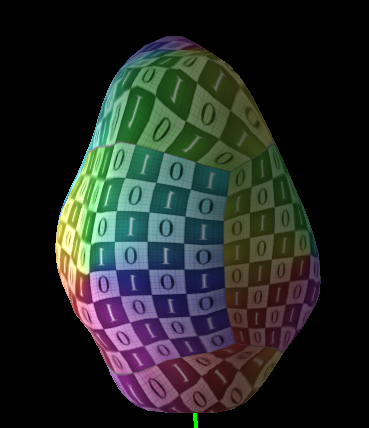
For the top face we take the x and z component of each point normalise the coordinate to be a portion of the current face. That will give us a correct texture coordinate for the face. And here is the result.
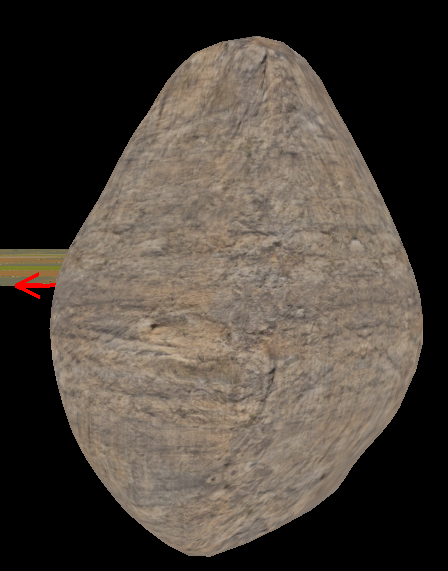
But as you can see, there is still distortion on some face due to the fact that I don’t take into account the depth component for each points which result in distortions !
Do you guys have any ideas on how I can make the texture stretch based on the depth of each face ?
I kinda wonder why do you want to wrap regularly (if that is what you want) a cubic texture on initially spherical object… isn’t it easier to generate a spherical one, or at least a cylindrical one first? Because otherwise I can’t see how could you get rid of corner point distortions wherever they lay on the end object. And it’s harder to control a nature of particular distortion this way imho.
Even if that’s not perfect. (I might have misapprehended the technique I think it be really close to what triplanar is meant to achieve) @Torsion
In fact I want to be able to procedurally apply texture on the mesh. (Blender has something called Minimize Stretch and I wanted to know how to simulate this behavior)
Minimize Stretch
Reference

Mode: View mode
Menu: UVs ‣ Minimize Stretch
Hotkey: Ctrl-V
The Minimize Stretch tool, Ctrl-V, reduces UV stretch by minimizing angles. This essentially relaxes the UVs.
Your idea was to generate a spherical texture based on the cubic texture ?
Just it looked a bit strange from the beginning, if I’d want to compensate non-uniformity of a distorted sphere I’d start from ideally covered ideal sphere, which is achieved through appropriate texture for spherical mapping (like Earth/Moon/Mars textures all around google)… but in topic description you refer to a distorted cube so maybe it is your 1st picture that misleaded me. Speaking of spherical map, there would be just two special cases on poles instead of 8 corners on a cubic map - but depending on your texture there might even be no need to do anything on them. So yes, if starting from sphere, I’d start from the texture for sphere…
In fact a normalized cube is a basically a cube subdivided into a sphere. (cf : gamedevdaily.io).
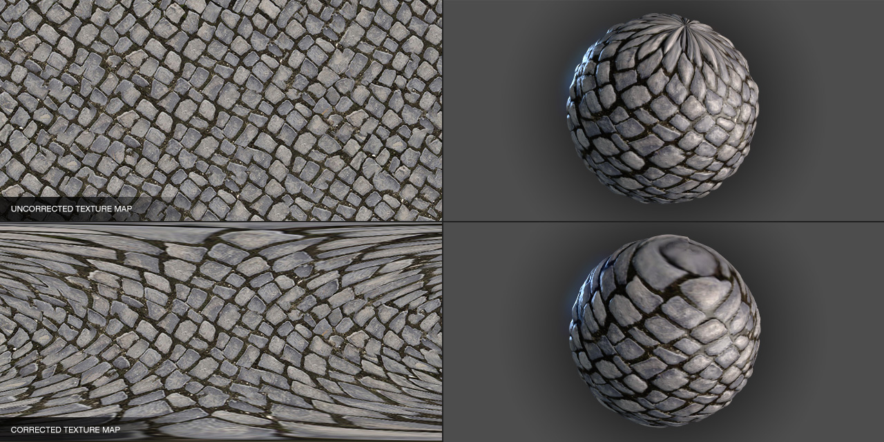
The method your are mentioning must be something like that
But I don’t really find this method appealing since the poles of the sphere are still distorted (less information which results in a strange pixels mess on the poles). My aim was to reduce the texture stretching as much as possible from a normalized cube with a cubic texture.
Totally out of the subject but I need a shader guru to help me. I’m working with your shader node system. What is the best way to integrate the lighting process into my material. Do you have a shader node definition already defined somewhere ? I couldn’t find it here
Or should I create my own lighting shader node to wrap your lighting shader behaviour ?
Right, these are two special cases that probably should be treated separately (i.e. you could replace mapping there with small polar tiles (representing spherical area) or something. I don’t insist it is faster or better, it was just something that popped out once I saw your pictures Anyway, your approach is interesting, why not
…then you end up with distortions where the tiles meet up because it ends up being exactly the same problem as the projected cube.
The projected cube is just pole tiles taken to the extreme, really.
To the original problem, I thought you could just reproject the cube onto the new coordinates but I guess since your object is no longer ‘equilateral’ (so to speak) that it would stretch anyway.
Agree, but that was more in response to “detail loss” problem. Generally, if you don’t want to see distortions at all you have to have 1 tile == 1 pixel, extremely speaking. Any other way implies additional constraints to the texture and/or to mapping mechanism, obviously. My point was that treating two cases could be probably easier than 8, nothing more. This doesn’t eliminate texture preparation need completely ofc.
I just made a test to see how I would proceed if I wanted to have a custom lighting node. For those in need for a quick and dirty node without anything but basic light computation. No specular and no parameter whatsoever.
@nehon
I just realised the amount of work to translate the entire shader library into the shader node system… I would like to help you but I don’t really know how to proceed since you might have your own idea on how you will do it. I just realised that you can’t really afford to have the old shader method and the new shader node in the core since modifying one would implies modifying the other. How are you going to proceed ? Merge the old system with your shader node system ? Make a script to translate one to another ?
 If you want any more information just ask