Blender PBR materials

yes, and now i think, if its better to have texture UV coords like separate head / legs / hands, or have everything connected only with one seam what split everything(that anyway this seam would make difference)

if there would be only texture, it looks fine, because blender add 10 pixels margin, so it have same colors in both separated coords. but metalness/normal make differences

I gave up on a humanoid model project because I could not the the seams correct.

yes, looks like character making is hardest thing i done too :smiley:

fact, it dont look so bad, but i need proper model for FPS style, not third person, so i need better result ;/

jjjjjjjj

I got stuck at : my uv islands can not line up correctly, so my tangets and binormals were wrong at every seam =/

you know what i do?

i draw in blender, but not like in paintā€¦ no noā€¦ i use premade texture in gimp or photoshop, and blender have tool to ā€œcloneā€ texture into mesh visually. Also set up 10 margin pixel to avoid seams anyway.

here is example video how it look:

1 Like

ty for sharing.

My issue is not seam margins, its the fact the edges of the seam islands do not point the same way in the uv layout as the seams they join, so each edge has a completely different tangent =/

this technique has me very interested right now :

1 Like

awesome video :smiley: so much to learn. i hope month will be enough for me to do decent character. we will see

Iā€™m not sure I can help much.

I make all my textures outside of blender and just import them.

I found that I could get better results for normal maps in Gimp using the Normalmap plugin or Materialize. Just depends on the texture mostly for which produced best results.

The gltf exporter uses the png format for pbr materials. At least thatā€™s what they say in the documentation. Remember not to compress the normal maps when exporting them. I think blender compresses png images by default unless you tell it not to.

Using materialize makes it easy to edit textures on the fly. You can use gimp to edit the texture and just hit buttons in materialize to reload and see instant results.

This is the node setup I found worked best. Its based on this article at khronos group. I use the glTF2_Principled.blend and append them from the material folder.

In this particular instance, I have packed the image as is instructed here. You can use gimp or materialize to pack the images. Materialize is fastest and easiest since you can set it up to match jmonkeys use of PBRLighting material def.

and toggling the LightMapAsAOMap toggle if using AO. This allows the use of one image for all three maps.

I found that the best way to fully test everything after setting up the nodes in blender was to use gimp to edit the image, export to shared folder for materialize, gimp and blender, use materialize to fine tune the images, reload the images using the Blender TexTools addon, export to jme project and load it into the game.

Blender Textools helped me to make my UV maps extremely clean when compared to relying just on default blender tools. It reveals a ton of bad things about the UV that blender just doesnā€™t. Like flipped meshes, crappy angles. unaligned uv, gaped uvs. That tool may help solve some of your seam problems.

That is about it I guess.

Edit: Forgot to mention, you probably know this but using the packed image will generate a warning about the use of linear colorspace. You can ignore it or as I did I just duplicated the PBRLighing def and set the -LINEAR flag on the lightmap variable since I dont use lightmaps.

1 Like

thanks. i will need to look at your solution. btw. i use materialize, but i use different nodes. and i dont pack it, but will need.

about UV map clean, did you try use UV map pins?

imo below look clean enough, its much better with textools? pins were already good for me always.
(image with red dots - red dots are pins ofc.)

nnnnnnnnnnnnnnn
nnnnnn

also i was googling, and found that some people create(bake) different UV coords for NormalMap(but without seams i think) and it solve seam issues.

But not sure, but is JME possible to have 2 UV coords for each texture different? as i remember i dont seen split for UV coords. so this solution will not work i think.

so now i really dont know how to make it properly. making normalMap manually, will anyway have seams, UV map would need have all faces connected. i will try bake some blender normalmap, but not sure if will help.

Im not sure if the node setup would help but I know that there is a whole lot more going on when you open up the Node groups from these nodes vs what you are doing with your setup.

That works for some meshes but for other meshes there are better ways. Its not really helpful for things like buildings where you are dealing with squares or clearly defined angles and no stretching. The textools works better for those. It works in conjunction with the blender tools not instead of so you can use it as needed and mix the two.

I have not used the baking part yet but everything else so far and the UV layout tools are awesome.

The mesh may look fine until you run the textools select tools like flipped(in edit mode with select all) or from the blender uv tools select>all by trait>loose and interior(in edit mode-wireframe with none selected).

Blender sucks at unwrapping in other words. It may look good like your does untill you dig a little deeper.

Iā€™m not sure how familiar you are with blender but another good thing to do is in the uv image editor, select hotkey N and toggle Stretch under display. Blue is good. Anything else may need to be looked into.

As for normal maps, I have not had a problem with seams yet so cannot help there. For the most part I cant see any benefit to using a normal map for certain things , like skin or clothes. The differences are so subtle it may not be worth the effort. What I have seen in the engine is you have to really exaggerate things to get good results so most things tend to be screwed up like your experiencing. Your normal map looks to strong to me. I am no expert though.

How you build a normal map though is really important. I have an article that really helped me to understand how to make good normal maps. You probably ran across it already though id imagine.

Boiling this tutorial down you will see that the best normal maps come from images with very limited numbers of color. How you limit the colors varies by image. In your case of skin, it looks like it should be closer to an all black image. The edges need to be shallower so darkening the overall image to be closer to the nipple color of black will smooth out the edges. That may solve your problem.

Edit: By darkening, I mean darkening your heightmap since that looks to be what you are using to build the normal map. Make it darker gray where the nips and such are black.

Edit: I cant tell where you get the normal map from since the normal is a negative. Are you supplying it or using heightmap or diffuse to generate it?

If you generate it from the heightmap, the contrast should be reversed so the nips and pelvic are the color the skin currently and the skin is dark gray. Realistically, the only thing showing on the normal map should be the nips and the pelvic bumps.

1 Like

You know what I find interesting is the first thing I do when I play a 3d game is to turn off every graphic control I can to strip the game down to the bare minimum so i never see any of this kind of detail. It has a pretty drastic affect on game play and to me that is more important than visuals.

I am old school though and game control take precedence over appearance.

Today, you can get rich off visuals (or vanity as I call it) it seems.

1 Like

sounds like a gaping hole, graphics should never effect the actual game play (exceptions like Splatoon). Turning down graphics to get rid of foliage or smoke in FPS is a good example of this problem.

I fell into this pit when using LOD physics objects by accident.

1 Like

Some people have better connections and video cards and may be closer to the server so sometimes small things like this can make a difference. That has been my experience for all games. My crap setup could only compete if I did things like that.

1 Like

What are those bumps, eyes and ear holes?

1 Like

you mean how it look like?

this are tiny elements.

i will try this tool what you tell about, i was afraid when blender will change version and it will stop work, so UV will break or something, but if you say its separate tool, so blender one stay intact, then why not.

also thanks for tips about normal map, i knew some of them, but will try find best solution.

One more question. How do you import .gltf format into JME. I mean i seen there is possibility load it directly, but IDE dont recognize it, so not sure how to preview models from IDE.

https://imgur.com/a/TS6lNi3

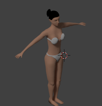
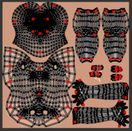
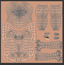
What is the mesh the yellow arrow points to? The head?

Are the bumps circled in red the eyes and ear holes?

Overall, the normal map is sunken in or in other terms negative and smooth. I donā€™t see how this could be a benefit so I am not sure if it should even be used at all in this situation. Shouldnā€™t a skin diffuse map just be a seamless tiled texture? This looks like a loaded baked texture with maps made from it. I havenā€™t seen this before except when texture painting on an exported uv map that you will re import back into blender.

Maybe someone could explain this technique or show me a link to it with respect to pbr materials.

You add the gltf exporter to blender. Currently, this 2.79 version has two scripts, one for import one for export.

You use the glTF2_Principled.blend I linked to for appending the nodes. The other links show you how to setup and use the blender nodes as well as the art creation pipeline. Appending is as simple as having the blender node editor open and just appending from the file menu. For each material, you append a new node from the pricipled.blends material folder. It will populate with all the nodes above. Just rename the material and connect the links.

I tried to use the way you and others use but the script and the blender BSDF shader just wouldnā€™t work for me.

This is all included in the newly released Blender 2.8 beta and ready to use if you upgrade blender but that may open up a whole new can of worms.

2.8 may require relearning of things. Not sure yet myself.

As to the process. once the scripts are working, you just export to your project, convert the gltf to j3o and either add it into a project or open the j3o in SDK scene explorer. Best to open in SDK first so you can generate tangents for it if need be, check animations and get a quick idea if something failed along the way.

I have a project that is already configured for animations, movement and has a light probe that I use for experimentation so I load the j3o and play with it.

There is TestPBRLighting in the jme test classes you can use to setup your probe.

This is all real easy and fast once the tools are all configured. In materialize, you can pack textures.

https://imgur.com/a/zDJQZht

Just click the buttons under Property Maps and set things up. You can then save that image and use it for your pbr setup in blender I showed above.

As long as you use the same image folder for gimp, blender and materialize, you are just reloading things after edits.

Edit in gimp and export, edit in materialize and save, reload with Blender textools, export to your project, convert and just run the project or open j3o in SDK scene explorer and run it from there.

1 Like

convert the gltf to j3o

not sure why but now i got it working, before IDE dont recognize it as ā€œconvertableā€ file. maybe just needed to restart IDE.

the circles are in torso and this are ā€œarms holesā€ there is seam that separate arms, thats why there is hole, same about bottom holes. Holes are small because normalMap is created based on ā€œ10 pixel margin albedo textureā€.

Head is above this torso, no holes there(probably because of margin" and its ok, because there should not be holes overall.

Hi again, already ask @thetoucher but maybe someone had similar issue.

I export character via gltf to JME. convert to j3o.

Then i add directional light - it work

Then i add ambient light - it dont work

Generate tangents (with only some of verticles exceeding angle) dont help (but not sure why i need select mirrored UV - what is it for anyway?)

Also when i change material to Phong then ambient work fine

So my main question is if someone know solution to fix ambient lighting work. When in sceneEditor i click camera light, it work fine, point light also work fine, Just ambient light dont work.

If itā€™s PBR then you need a light probeā€¦ else there is no ambient.

1 Like

i thought light probe is only needed for ā€œenv camera reflectionā€(metalness)

About light probes i thought i will have one near main character with range like 100(so only near elements would use) and its still possible, but its range should be then like 100000 units, to make distant models have just ambient?

why camera light / directional light / point light still works without probe?

when i add light probe, then ambient dont affect anyway, so light probe is as ambient for PBR?