    public void Camera() {
        Vector3f[] points = new Vector3f[8];
        for (int i = 0; i < 8; i++) {
            points[i] = new Vector3f();
        }

        Camera frustumCam = cam.clone();
        frustumCam.setLocation(new Vector3f(0, 0, 0));
        frustumCam.lookAt(Vector3f.UNIT_Z, Vector3f.ZERO);
        frustumCam.setFrustumFar(500f);
        ShadowUtil.updateFrustumPoints2(frustumCam, points);
        Mesh mesh = WireFrustum.makeFrustum(points);

        Geometry frustumGeo = new Geometry("MiniCam", mesh);

        Material mat = new Material(simpleApp.getAssetManager(), "Common/MatDefs/Misc/Unshaded.j3md");
        mat.setColor("Color", ColorRGBA.White);
        mat.getAdditionalRenderState().setWireframe(true);

        frustumGeo.setMaterial(mat);
        frustumGeo.setCullHint(Spatial.CullHint.Never);
        frustumGeo.setShadowMode(RenderQueue.ShadowMode.Off);

        simpleApp.getRootNode().attachChild(frustumGeo);
    }
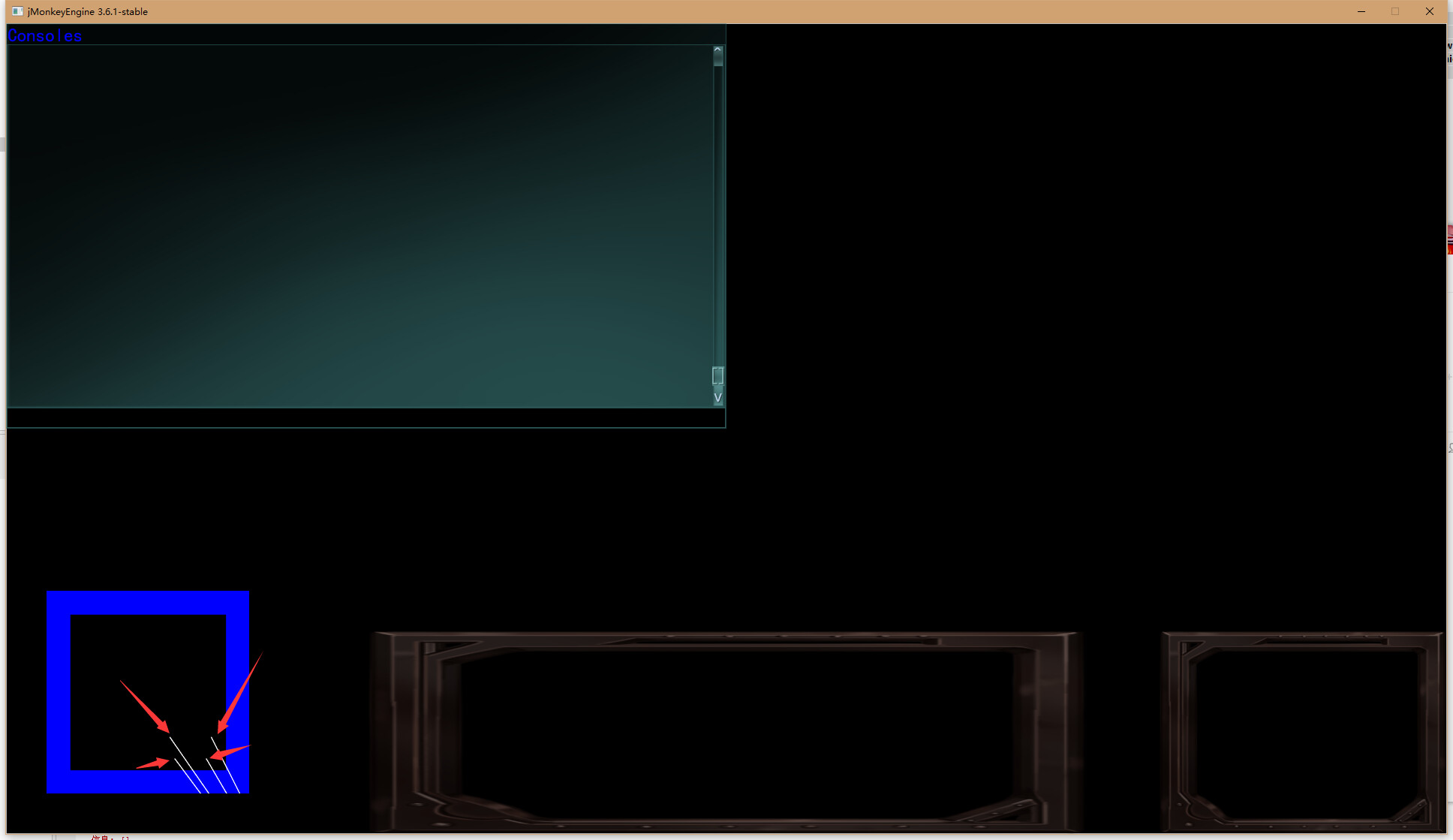
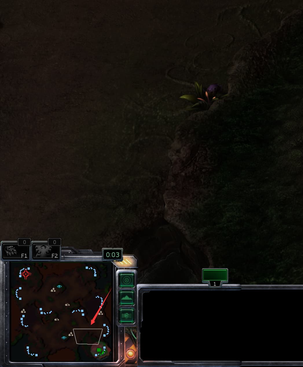
I use this code to draw the trapezoid of the camera, the four diagonal edges of the trapezoid pass through the map exactly where they form a flat trapezoid, how do I draw this trapezoid on the mini-map?
It looks like this.
codex
March 19, 2024, 10:02pm
2
Cast four rays from the camera along the frustum and test them against a plane. Then construct a mesh from the collision points.
1 Like
pspeed
March 19, 2024, 10:40pm
3
Was going to say exactly this.
It’s not particularly elegant but it’s straight-forward and will definitely work.
1 Like
 // 获取屏幕上的点的世界坐标
        Vector3f click3d0 = cam.getWorldCoordinates(new Vector2f(0,0), 0f);
        Vector3f click3d1 = cam.getWorldCoordinates(new Vector2f(cam.getWidth(),0), 0f);
        Vector3f click3d2 = cam.getWorldCoordinates(new Vector2f(cam.getWidth(),cam.getHeight()), 0f);
        Vector3f click3d3 = cam.getWorldCoordinates(new Vector2f(0,cam.getHeight()), 0f);

            // 计算方向
            Vector3f dir0 = click3d0.subtract(cam.getLocation());
             Vector3f dir1 = click3d1.subtract(cam.getLocation());
              Vector3f dir2 = click3d2.subtract(cam.getLocation());
               Vector3f dir3 = click3d3.subtract(cam.getLocation());

            dir0.normalizeLocal();
            dir1.normalizeLocal();
            dir2.normalizeLocal();
            dir3.normalizeLocal();

        // 创建射线并进行碰撞检测
        checkCollisionWithRay(new Ray(click3d0, dir0), iresults);
         System.err.println(iresults.getClosestCollision().getContactPoint()+",cam0");
         vertices[0]=iresults.getClosestCollision().getContactPoint().x;
         vertices[1]=1;
         vertices[2]=iresults.getClosestCollision().getContactPoint().z;
         iresults.clear();
        checkCollisionWithRay(new Ray(click3d1, dir1), iresults);
        System.err.println(iresults.getClosestCollision().getContactPoint()+",cam1");
        vertices[3]=iresults.getClosestCollision().getContactPoint().x;
        vertices[4]=1;
        vertices[5]=iresults.getClosestCollision().getContactPoint().z;
        iresults.clear();
        checkCollisionWithRay(new Ray(click3d2, dir2), iresults);
         System.err.println(iresults.getClosestCollision().getContactPoint()+",cam2");
         vertices[6]=iresults.getClosestCollision().getContactPoint().x;
         vertices[7]=1;
         vertices[8]=iresults.getClosestCollision().getContactPoint().z;
         iresults.clear();
        checkCollisionWithRay(new Ray(click3d3, dir3), iresults);
         System.err.println(iresults.getClosestCollision().getContactPoint()+",cam3");
         vertices[9]=iresults.getClosestCollision().getContactPoint().x;
         vertices[10]=1;
         vertices[11]=iresults.getClosestCollision().getContactPoint().z;
         iresults.clear();


        mesh.setBuffer(VertexBuffer.Type.Position, 3, vertices);
        mesh.setBuffer(VertexBuffer.Type.Index, 3, BufferUtils.createShortBuffer(indices));
        mesh.updateBound();
       Geometry gridGeometry = new Geometry("camT", mesh);
       Material Material = new Material(assetManager, "Common/MatDefs/Misc/Unshaded.j3md");
       Material.setColor("Color", ColorRGBA.White);
       Material.getAdditionalRenderState().setWireframe(true);
       gridGeometry.setMaterial(Material);
       simpleApp.getRootNode().attachChild(gridGeometry);
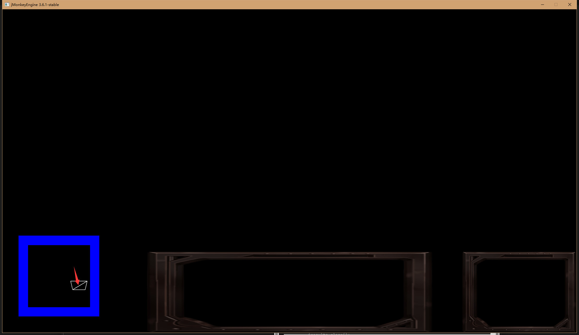
I use this code to draw trapezoidal
Since it’s made up of two triangles with an extra line in the middle, how do I make the line in the middle disappear?
codex
March 20, 2024, 11:59am
5
You’d have to use a different mesh mode that doesn’t draw triangles:
Mesh mesh = ...
mesh.setMode(Mesh.Mode.LineLoop);
LineLoop may or may not require an index buffer; the documentation is not all that clear.
1 Like
Mesh.Mode.LineLoop and Mesh.Mode.Lines do not ‘Require’ setting index buffer manually, but will appear as a broken chain of line segments due to the fact that the next segment startpoint needs to overlap the last segments endpoint, eg:
but not setting an index buffer manually will default to indexing the vertices sequentially, eg:
pspeed
March 22, 2024, 7:16pm
8
And when the vertex count is already small (like this), sometimes the index buffer doesn’t really save any size.
v1, v2, // 6 floats
v2, v3, // 6 floats
v3, v4, // 6 floats
v4, v5 // 6 floats
-----------
36 floats = 144 bytes
versus:
v1, v2, v3, v4 // 12 floats  = 46 bytes
0, 1, 1, 2, 2, 3, 3, 4 // 8 int = 32 bytes
A difference, but not a large one unless you have other vertex attributes. You could also use byte or short for the index.
Personally, for line meshes, I just make buffers with duplicate vertexes and don’t worry about an index.
All of the above only applies to Lines. For a line loop with no additional attributes, the index buffer is a 100% waste of space.
4 Likes