Own Frag Shader has an ugly edge on the texture coordinate setback

This is my first time tinkering with the shader. I don’t want to use tex.setWrap (WrapMode.Repeat) in the texture;. I thought to myself, that I could simply reset the texCoord1 in the Frag Shader instead. It is best to understand using a numerical example:

a) The texture should be a 4x4 tile large atlas.
b) A tile is then 0.25f wide.
c) texCoord1.x is taken from [0.25, 0.75[
d) but repetition = 2
e) then texCoord1a.x would be from [0.25, 0.50[ + then either [0.25, 0.50[, simply always subtract a width of 0.25 started from the first 0.50.
f) the repetition is calculated like this:
int repatX = int (texCoord1.z);
vec2 texCoord1a = vec2 (texCoord1.x - repatX * 0.25, texCoord1.y - repatY * 0.25);
where texCoord1.z is from [0, 2[. (I define texCoord1 as vec4)
g) then color * = texture2D (m_ColorMap, texCoord1a);

Analogue bogged down in y with texCoord1.w.

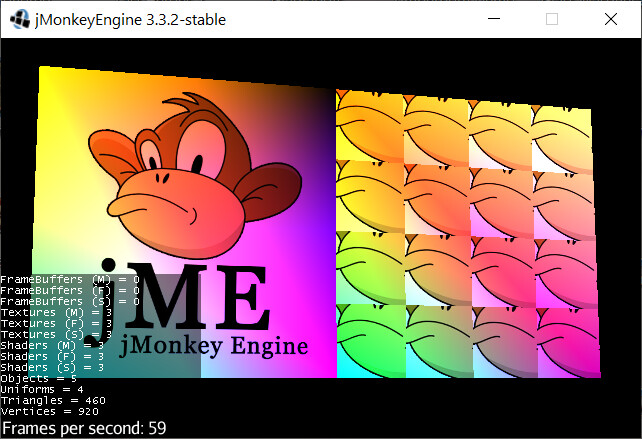
Fun actually works great, but I have unsightly effects on the line between the tiles. Suspect something with biliner rendering or something like that.

How can I solve the problem?

Here is the picture, a bit colorful, because I sat on my previous gradient test.
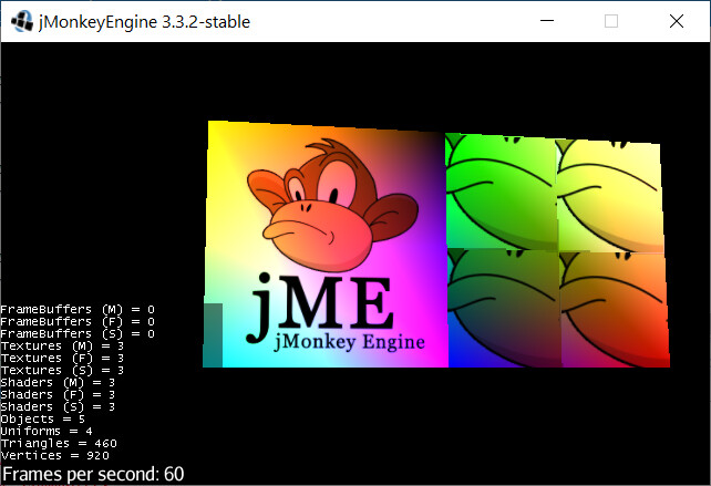
It is not due to the colors, retest with

colors [4] = new Vector4f (1, 1, 1, 1);
colors [5] = new Vector4f (1, 1, 1, 1);
colors [6] = new Vector4f (1, 1, 1, 1);
colors [7] = new Vector4f (1, 1, 1, 1);

the weird line (medium - dark - light - medium transition):

from the square on the right:
image

code, java:

package test.jme;

import com.jme3.app.SimpleApplication;
import com.jme3.material.Material;
import com.jme3.math.Vector3f;
import com.jme3.math.Vector4f;
import com.jme3.scene.Geometry;
import com.jme3.scene.Mesh;
import com.jme3.scene.VertexBuffer;
import com.jme3.texture.Texture;
import com.jme3.util.BufferUtils;

public class TestGradient extends SimpleApplication {

	private Material mat;

	public static void main(final String[] args) {
		final TestGradient app = new TestGradient();
		app.start();
	}

	@Override
	public void simpleInitApp() {

		// the points in 3d space where the geometry will be
		final Vector3f[] vertices = new Vector3f[8];
		// one square
		vertices[0] = new Vector3f(0, 0, 0);
		vertices[1] = new Vector3f(3, 0, 0);
		vertices[2] = new Vector3f(0, 3, 0);
		vertices[3] = new Vector3f(3, 3, 0);
		// a second square
		vertices[4] = new Vector3f(3, 0, 0);
		vertices[5] = new Vector3f(6, 0, 0);
		vertices[6] = new Vector3f(3, 3, 0);
		vertices[7] = new Vector3f(6, 3, 0);

		// combine those vetexes into triangles
		final int[] indexes = {
				// first square
				2, 0, 1, 1, 3, 2,
				// second square
				6, 4, 5, 5, 7, 6 };

		// we're not using a texture but if we were this would define whtich parts of
		// the image are where
		final Vector4f[] texCoord = new Vector4f[8];
		texCoord[0] = new Vector4f(0, 0, 0, 0);
		texCoord[1] = new Vector4f(1, 0, 0, 0);
		texCoord[2] = new Vector4f(0, 1, 0, 0);
		texCoord[3] = new Vector4f(1, 1, 0, 0);
		texCoord[4] = new Vector4f(0.25f, 0.40f, 0, 0);
		texCoord[5] = new Vector4f(0.75f, 0.40f, 2, 0);
		texCoord[6] = new Vector4f(0.25f, 0.90f, 0, 2);
		texCoord[7] = new Vector4f(0.75f, 0.90f, 2, 2);

		final Vector4f[] colours = new Vector4f[8];
		// these are Vector4f because we have a red, green, blue and transparency per
		// vertex
		colours[0] = new Vector4f(0, 2, 1, 1);
		colours[1] = new Vector4f(1, 0, 2, 1);
		colours[2] = new Vector4f(2, 1, 0, 1);
		colours[3] = new Vector4f(0, 0, 0, 1);

		colours[4] = new Vector4f(0, 0, 1, 1);
		colours[5] = new Vector4f(1, 0, 0, 1);
		colours[6] = new Vector4f(0, 1.5f, 0, 1);
		colours[7] = new Vector4f(2, 2, 2, 1);

		// now we have all the data we create the mesh
		// for more details
		// https://jmonkeyengine.github.io/wiki/jme3/advanced/custom_meshes.html
		final Mesh mesh = new Mesh();
		mesh.setBuffer(VertexBuffer.Type.Position, 3, BufferUtils.createFloatBuffer(vertices));
		mesh.setBuffer(VertexBuffer.Type.Index, 3, BufferUtils.createIntBuffer(indexes));
		mesh.setBuffer(VertexBuffer.Type.TexCoord, 4, BufferUtils.createFloatBuffer(texCoord));
		mesh.setBuffer(VertexBuffer.Type.Color, 4, BufferUtils.createFloatBuffer(colours));
		mesh.updateBound();

		final Geometry geom = new Geometry("mesh", mesh);

		//mat = new Material(assetManager, "Common/MatDefs/Misc/Unshaded.j3md");
		mat = new Material(assetManager, "assets/matdefs/JaReUnshaded.j3md");
		mat.setBoolean("VertexColor", true);
		final Texture monkeyTex = assetManager.loadTexture("Interface/Logo/Monkey.jpg");
		mat.setTexture("ColorMap", monkeyTex);

		geom.setMaterial(mat);

		rootNode.attachChild(geom);
	}

	@Override
	public void simpleUpdate(final float tpf) {
	}
}

code frag shader:

#import "Common/ShaderLib/GLSLCompat.glsllib"

#if defined(HAS_GLOWMAP) || defined(HAS_COLORMAP) || (defined(HAS_LIGHTMAP) && !defined(SEPARATE_TEXCOORD))
    #define NEED_TEXCOORD1
#endif

#if defined(DISCARD_ALPHA)
    uniform float m_AlphaDiscardThreshold;
#endif

uniform vec4 m_Color;
uniform sampler2D m_ColorMap;
uniform sampler2D m_LightMap;

varying vec4 texCoord1;  //!JaRe!
varying vec2 texCoord2;

varying vec4 vertColor;

void main(){
    vec4 color = vec4(1.0);
    
    //!JaRe! begin
    int repatX = int (texCoord1.z);
    int repatY = int (texCoord1.w);
    vec2 texCoord1a = vec2(texCoord1.x - repatX*0.25, texCoord1.y - repatY*0.25);
    //!JaRe! ende

    #ifdef HAS_COLORMAP
        color *= texture2D(m_ColorMap, texCoord1a);     //!JaRe!
    #endif

    #ifdef HAS_VERTEXCOLOR
        color *= vertColor;
    #endif

    #ifdef HAS_COLOR
        color *= m_Color;
    #endif

    #ifdef HAS_LIGHTMAP
        #ifdef SEPARATE_TEXCOORD
            color.rgb *= texture2D(m_LightMap, texCoord2).rgb;
        #else
            color.rgb *= texture2D(m_LightMap, texCoord1a).rgb;    //!JaRe!
        #endif
    #endif

    #if defined(DISCARD_ALPHA)
        if(color.a < m_AlphaDiscardThreshold){
           discard;
        }
    #endif

    gl_FragColor = color;
}

code vert shader:

#import "Common/ShaderLib/GLSLCompat.glsllib"
#import "Common/ShaderLib/Skinning.glsllib"
#import "Common/ShaderLib/Instancing.glsllib"
#import "Common/ShaderLib/MorphAnim.glsllib"

attribute vec3 inPosition;

#if defined(HAS_COLORMAP) || (defined(HAS_LIGHTMAP) && !defined(SEPARATE_TEXCOORD))
    #define NEED_TEXCOORD1
#endif

attribute vec4 inTexCoord;     //!JaRe!
attribute vec2 inTexCoord2;
attribute vec4 inColor;

varying vec4 texCoord1;     //!JaRe!
varying vec2 texCoord2;

varying vec4 vertColor;
#ifdef HAS_POINTSIZE
    uniform float m_PointSize;
#endif

void main(){
    #ifdef NEED_TEXCOORD1
        texCoord1 = inTexCoord;
    #endif

    #ifdef SEPARATE_TEXCOORD
        texCoord2 = inTexCoord2;
    #endif

    #ifdef HAS_VERTEXCOLOR
        vertColor = inColor;
    #endif

    #ifdef HAS_POINTSIZE
        gl_PointSize = m_PointSize;
    #endif

    vec4 modelSpacePos = vec4(inPosition, 1.0);

    #ifdef NUM_MORPH_TARGETS
        Morph_Compute(modelSpacePos);
    #endif

    #ifdef NUM_BONES
        Skinning_Compute(modelSpacePos);
    #endif

    gl_Position = TransformWorldViewProjection(modelSpacePos);
}

P.S.: Many thanks to richtea for a source code (two squares) that i am using here.

1 Like

Atlases and filtering don’t mix without spacing between them… a border space where you can repeat some number of pixels from the texture. Else you will get bleed from the next texture in the atlas.

Unless you turn off the mag filter like minecraft pixelated textures.

Is there a reason that you want to use a texture atlas instead of a texture array?

Edit: for minecraft style textures and to prove that it “fixes” this issue (and probably creates new ones):
https://javadoc.jmonkeyengine.org/v3.3.2-stable/com/jme3/texture/Texture.html#setMagFilter-com.jme3.texture.Texture.MagFilter-

https://javadoc.jmonkeyengine.org/v3.3.2-stable/com/jme3/texture/Texture.MagFilter.html#Nearest

Thank you very much.

Why?

  1. I thought it was a good idea until it went wrong :).
  2. However, the neighboring pixels in the test atlas have the same color (monkey face) – at least no problem here.
  3. “You don’t do it like that”, is an acceptable answer, but doesn’t really explain why it goes wrong (or I didn’t understand the essence of the answer).
  4. Could I manipulate texture2D or the Texture.MagFilter so that I am left and right convergent at the edges in question?
  5. Then I’ll learn more about texture array first
    5a. Can I then use multiple textures from a texture array in the same single mesh?

Edit: P.S. I can quickly solve that with the neighboring tile, e.g. tile width is 0.23 instead of 0.25, offset 0.01. So Atlas has 0.01 + 0.01 margins. But that can’t be the reason here!

Oh yes. And because the instructions only talk about Optimization: Texture Atlas.

Looking deeper…

At the edges of your quads (when they are angled on screen) it’s possible for these texture coordinates to drift not only above but also below the values. So sometimes they will be one cell off of where you want.

If you really want to do atlases then you have to have a coordinate that is the atlas cell and do not interpolate it. Then interpolate regular corner texture coordinates and map and clamp them to the cell.

So for example, leave regular TexCoord as your 0…1 style texture coordinates like any normal quad. Then have a TexCoord2 be the atlas coordinate. When setting it to the varying that the frag shader will use make sure the varying does not interpolate (flat qualifier). Then in the fragment shader you can clamp your TexCoord to 0…0.99 or whatever… multiply by 0.25 and use TexCoord2 to calculate the atlas cell basis.

Much easier to just use a texture array. The biggest limitation of texture arrays is that all of the textures in the array must be the same size… but that was already true for the atlas.

Yes, it’s like a 1-wide atlas that the GPU does the work for you.

O, yes, I want to do that. But I can’t find any instructions in the documentation … Could you still provide me with a link / example? Thank you very much.

By the way: monkeyTex.setMagFilter (Texture.MagFilter.Nearest); did not help either.

then this probably happens here:

I think jme-examples has one. That’s how I learned it.

Perhaps you’re thinking of TestTextureArray.java?

1 Like

Hi! It’s me again.

Thanks for the link, sgold, I was looking for it!

I know: we agreed that I would learn and use texture array.
However, everything I don’t know, makes me crazy and very jittery.

With your hints and intrusiveness towards the engine, I have solved my problem - even if I shouldn’t use it.
image

Changes:
in java:

		final Vector4f[] texCoord = new Vector4f[8];
	texCoord[0] = new Vector4f(0, 0, 0, 0);
	texCoord[1] = new Vector4f(1, 0, 0, 0);
	texCoord[2] = new Vector4f(0, 1, 0, 0);
	texCoord[3] = new Vector4f(1, 1, 0, 0);
	texCoord[4] = new Vector4f(0.25f, 0.40f, 0, 0);
	texCoord[5] = new Vector4f(0.25f, 0.40f, 4, 0);
	texCoord[6] = new Vector4f(0.25f, 0.40f, 0, 4);
	texCoord[7] = new Vector4f(0.25f, 0.40f, 4, 4);

and monkeyTex.setMinFilter(MinFilter.BilinearNoMipMaps);

in frag shader:

//!JaRe! begin
int repatX = int (texCoord1.z);
int repatY = int (texCoord1.w);
float texX = min(127.0/128.0,max(0,texCoord1.z - repatX));
float texY = min(127.0/128.0,max(0,texCoord1.w - repatY));
vec2 texCoord1a = vec2(texCoord1.x + (texX)*0.25 , texCoord1.y + (texY)*0.25);
//!JaRe! end

What does “NoMipMaps” mean. That saved everything. How bad is it?

Edit 1: Ah, here it is: Mip Mapping – Wikipedia

Edit 2: Understood: Since every texture is completed in array, the mipmap must be right or left convergent at the edges. In atlass the mip map does not know the edges.

thank you again.

Edit 3: But blender also creates an atlas. And Blender figures are certainly also mip mapped. So there are filters that can reduce the atlas taking into account the shape …

Now I’m restless again. Grrr.

Edit4: Of course, the question arises, how can I load a manually created mip map into a texture?

Well, actually I had planned for the future:

if (texCoord1.z <200) → use width m_width1 (here == 0.25)
elseif (texCoord1.z <400) → use m_width2
elseif (texCoord1.z <600) → use m_width3 as the tile width,

with the restriction that a maximum of 200 repetitions per triangle are allowed.

This is not that easy with array.

A blender atlas will (based on the skill of the modeler) try to keep obvious seams together in the texture to avoid this issue. This is why UV wrapping can be quite an art… picking the proper edge of the model to ‘cut’ for the UV map. Then usually Blender will have additional pixels in the gaps to keep mip blending smooth.

At some point, you can continue to make more and more complicated shaders… or you can have three materials that use texture arrays. Given that this stuff is like 5% of what it takes to make a whole game, I recommend spending as little time on it as possible.

…unless finishing a game is not your goal. Then continue.

Small note: With normal textures mip maping seems to be switched on automatically, with array texture not at first.

Only when I expressly ordered MinFilter.BilinearNearestMipMap after the changeover (old try → array texture) was the result comparable to the first test:

arrayTexture.setMinFilter (MinFilter.BilinearNearestMipMap);

Good in that I’ve racked my brain. Now I knew then what I needed. :grin: