Passing custom per-vertex data not working

Hey All!

TL;DR: I can’t pass neither integer nor float custom values to my shaders properly.

In depth:
I’m working on a shader and I need to pass in 4 integer values per vertex. I’ve read on this forum that I can’t create a custom buffer type but JMonkeyEngine is flexible so I can use other unused buffers so I choose TexCoord7.

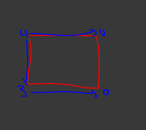
I have the following mesh, which is a quad for demonstration purposes:

App.java

        Mesh m = new Mesh();

        // Some code here to set up a quad with 4 vertex, texture coordinates and normals.
        // ...

        // Custom 4 integers I want to add per vertex
        float[] blendIndexes = {
                0, 2, 2, 2,   // for vertex 0
                1, 2, 2, 2,   // for vertex 1
                0, 3, 3, 3,   // for vertex 2
                3, 3, 3, 3    // for vertex 3
        };

       // ...

        m.setBuffer(VertexBuffer.Type.TexCoord7, 4, BufferUtils.createFloatBuffer(blendIndexes));

Vertex shader

    attribute vec4 inTexCoord7;
    flat varying vec4 blendIndex;

    // ...

    blendIndex = inTexCoord7;

Fragment shader

    flat varying vec4 blendIndex;

    //...

    // Simple visual debug: set diffuseColor to black and turn it to red if blendIndex.x is 0. But it is never 0. But on the custom data, the first vertex should have 0 value in the custom integers' x component.
    vec4 diffuseColor = vec4(0.0, 0.0, 0.0, 1.0);    
    if(blendIndex.x == 0.0) {  // This should make my quad partially red because blendIndex.x should be 0.0 for the first vertex but it is not 0.0.
        diffuseColor.r = 1.0;
    }

I figured out the problem lies between passing the custom values to the vertex shader, because if I do this in the vertex shader then my quad turns red where it should be:

Modified Vertex Shader

    // blendIndex = inTexCoord7;
    blendIndex = vec4(0.0, 2.0, 2.0, 2.0); // This works. I just set values here manually. Of course this will be same for all vertices but we're debugging.

I also tried passing in the custom data in different ways:

// Tried different types..
float[] blendIndexes = { 0.0, 2.0, 2.0, 2.0.....}
int[] blendIndexes = {0, 2, 2, 2.....}

// Tried setting the format to Float..
m.setBuffer(VertexBuffer.Type.TexCoord7, 4, VertexBuffer.Format.Float, BufferUtils.createFloatBuffer(blendIndexes));
// ...and to Int.
m.setBuffer(VertexBuffer.Type.TexCoord7, 4, VertexBuffer.Format.Int, BufferUtils.createIntBuffer(blendIndexes));

Question: vec4 blendIndex in vertex and fragment shaders never has the proper custom values. What am I doing wrong?

Edit: edited question at the end

What is your mesh? Triangles? Something else?

Does it uses indexes? Are there only four vertexes?

The code we see looks correct to me. Using “flat” for the varying may affect what you see visually depending on the code we can’t see… for example, if those 0 vertexes are always the trailing edge then you will never see those colors.

If it were me, I’d start putting some real colors in the attribute and turning off ‘flat’ then set that attribute directly as the vertex color… just to see “something” then work backwards from there. In your current setup, there are two many things that can lie to your eyes (unfortunately the easiest way to debug shaders).

1 Like

My mesh is a plane consisting of 4 vertices and two triangles. It is the same as in the com/jme3/scene/shape/Quad.java class because I copied the code from there to a test app class and added the extra buffer with the integers.

for example, if those 0 vertexes are always the trailing edge then you will never see those colors.

What do you mean by this exactly? All my 4 vertices are on the edge since they are the four edge of the plane on two trianges. But let’s come up with an example: let’s say I have one triangle with vertices 0, 1, 2. I assign a number to each vertex as a custom float data: 0.5, 1.0, 2.0. If I wouldn’t use the flat keyword, they would be interpolated between the vertices and if I would visualize it it would look like the classic uv coordinate vizualisation when the red goes to green to yellow etc over the triangle’s surface.
If I would add the flat keyword that would mean that 0.5, 1.0 and 2.0 would stay the same value on all the pixels belonging to the given vertex on the surface of the triangle, right? And there would be a hard edge between them and not a transition and the triangle would be divided up two three sections with hard borders.

If it were me, I’d start putting some real colors in the attribute and turning off ‘flat’ then set that attribute directly as the vertex color…

Well, these integer values won’t be used as colors but as indexes to read a texture from a texture array. But I’m not there yet because these values change when they get to the vertex shader. Me setting diffuseColor to black and red was an attempt to color those pixels red in the triangle which belong to a vertex which has the 0 value as it’s first integer.

Edit: In general, would it be with hard borders between red green and blue on the image below instead of soft gradient if i use the ‘flat’ keyword? Maybe this tricks me because I have false knowledge about the topic.
image

I know that. But we are trying to debug whether the values are making it there or not at all. So we need to start removing things that could go wrong.

I mean that if all of the 0 vertexes are on the right edge and the fragments are being built left to right then you will never see 0.

This whole quad:
image
…will only see 4 if the fragments are being built top to bottom and left to right. The far left edge will be 4 for every fragment. The top edge will be 4 for every fragment.

Edit: put another way, I’ve never had even a slight problem getting my custom attributes into a shader. But I’ve had plenty of times I misinterpreted the values.

1 Like

Edit: put another way, I’ve never had even a slight problem getting my custom attributes into a shader. But I’ve had plenty of times I misinterpreted the values.

I’m 100% sure I’m not understanding something and I’m misinterpreting it.

…will only see 4 if the fragments are being built top to bottom and left to right. The far left edge will be 4 for every fragment. The top edge will be 4 for every fragment.

OMG, so if there is a fragment that is close to the bottom right corner but not completely in the corner, it will see the custom value ‘4’ but not the zero which it is the closest to??? This is what I missed. I have to rethink how to resolve this.

In general, I wanted to do this: I have voxels. If there is a dirt and there is a rock voxel next to each other, I want the dirt to transition over to rock. My idea was to store extra texture array indexes by vertex on those vertices that are in the rock but on the side which is next to the dirt. This way I would have had a small area where the dirt texture could transition into rock on the rock voxel itself. But according to what you have said, I can’t do that on edge vertices because the fragments belonging to them don’t see the extra texture array indexes.

If you want values to interpolate in any way across the shape then you need to not use “flat” because that turns off all interpolation. Whatever value starts that row will finish that row.

So, yeah, I don’t think your approach can work as is. If want to blend between different textures in an atlas then you will somehow have to encode all possible atlas cells represented at each vertex. Like, a 4x4 atlas you could have 16 floats for how much of each atlas cell is at a particular vertex… but as you can see, for a large atlas this becomes untenable… even for 16 you will effectively be doing 16 texture fetches in the end.

It’s not a straight-forward problem to blend block world (or other types of voxels) sides in a general sense. Usually it comes down to special materials that transition between only 2 or 3 at a time… and then clever placement.

2 Likes

@pspeed Thank you so much again for your patience and help! I’m gonna go research more and rethink this whole thing.

4 Likes