I’ve started working on texturing it and I’m running into… issues. I’ve determined that it’s probably to do with how I do either the vertices and/or how I assign texture coordinates. Just a quick bit of background first though.
Since the icosahedron I’m making starts as a 20 sided sphere made of equilateral triangles I thought to myself “HEY! All I need to do to make quads out of all that is pair up each triangle and boom!” After I had all the vertices sorted out and linked up I was able to make the shape I wanted easily. NOW to assign vertices.
Issue is that I want to assign textures to each quad. If this is arranged in a single texture the image could be huge to ensure each quad has a unique texture. So I thought why not just make a small set of the various variations and just have each quad select part of the texture instead?
Now comes the issue. I tried that and things didn’t work out well. But I think I have a solution but I need some clarification on texture coordinates in how they relate to vertices and quads.
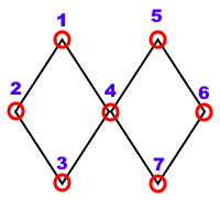
Say I have 1 texture that I want to apply across 2 quads that are linked at a similar vertice like so:
I link the left and right quads properly but they share a common vertice (number 4).
When I make the texture coordinate array is each texture coordinate linked to only 1 vertice? Or are they associated to the indexes array?
In the example given would there be an array of 7 texture coordinates or 8?
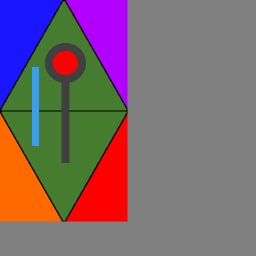
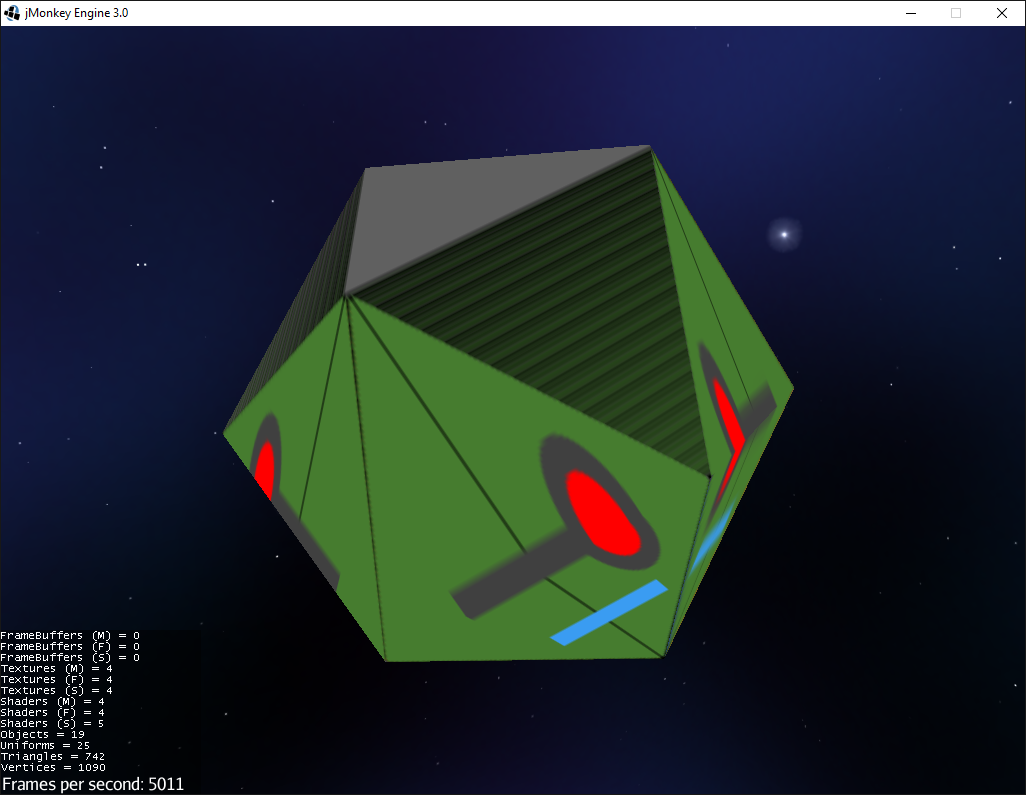
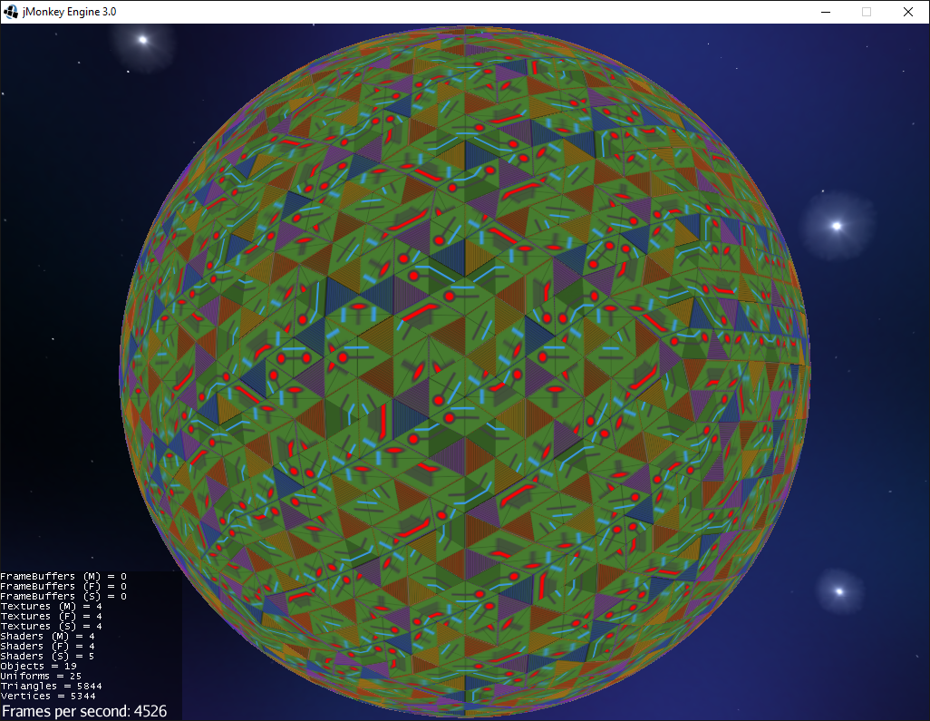
Just to show what issues I had here’s the texture I want to plaster over every quad (Just the green part, the colouring etc is just to help me figure out what the heck is going on).
As you can see some of it is twisted 90 degrees and some… has gone all weirdly stripey. It only gets worse when you add more subdivisions (although it is pretty)
Yes. To both. It seems like you are confusing things.
Things in the texture coordinate buffer, the position buffer, the normal buffer, the “insert favorite buffer here” buffer… are all in sync with one another. The index buffer just tells you which vertex to use… but a vertex is the position and all of the other attributes.
Well, there are many texture coordinate buffers so a single vertex can have a TexCoord1, TexCoord2, etc… but in the spirit of your question, yes, just 1.
In OpenGL a vertex is “all of the stuff”… not just position. So a unique vertex is unique because of all of its attributes. If the normal, texcoord, color, etc. are different for the same position then those are two different vertexes.
So to solve my problem I guess I’ll have to essentially create a single texture with enough quad pairs to cover the entire thing properly and not try to cheat like I did.
Without hacking shaders, that may be your only option. I wasn’t exactly sure what you were trying to do or how many different face textures you have… but there might be some shader tricks with multiple texture coord buffers that could work also.
If I could use multiple texture buffers that’d enable me to basically make a single unique texture for each type of quad on my sphere and just have the appropriate one called per quad no?
Clarification on that previous post. It just seems that the code provided in the tutorial is implying that you can only have 1 texture coordinate buffer.
Look at the Type class’s javadoc to see the other buffer types available.
But if you want to use multiple buffers you still have to deal with the regular ones. So some trickery is involved in the shader to layer them. It may not solve your problem.
Another option is to use different meshes that share all of the vertex buffers except the texture coordinates then just draw the mesh multiple times using transparent textures for the layers that don’t have that particular texture. This is similar to the shader version except it does multiple draw calls but it’s easier to debug, also.
hmmm… Ya. Not sure which option to pursue at this point now. Let me explain what I’m trying to accomplish maybe you can give me your opinion on how to proceed?
What I’m trying to do at this point is assign each tri a colour (If there was say 3 colours I’d have texture quads of say Green green, green red, green blue, red red, etc etc.). This colour is a unique tectonic plate.
After assigning each plate a direction to move (the meshes surface won’t actually move, I’m pretending where the plates are now is where they moved to), a movement strength/speed, and a base plate height I’d calculate things like mountains, plains, and crevices based on plate tectonics.
So assigning them colours is a sort of debugging step until I get to the point of actually figuring out the types of land that’d result from all these forces.
It’s sorta why I was thinkin of making textures as pairs of colours so that it’d be quads not tri’s. Would assigning colour to a vertex not run into a similar issue though? I mean… If the tri/quad is red and the neighboring one is blue the common edge between the 2 would be red blue?
That’s why I asked if the triangles/quads are really important. If things were vertex based then you wouldn’t have any issues… just assign colors to the vertexes and let the faces interpolate.
But if each quad (two tris, really, let’s be real) must have its own unique face then you are stuck with making each face have its own vertexes. It’s definitely the easiest way. Optimize later.
Perhaps what I can do is instead of saying a particular tri is part of a tectonic plate is say each vertex marks either a part of a plate or an edge of a plate. That may be the easiest solution for this currently.
Do you have a link to a doc or something about assigning colours to vertices?