Hi all. I’ve followed some advics and I started working on a separated project for my voxel engine, so I could have clearer ideas.
Following the advices I’ve something that works so:
-Setting vertices in the space (16 for each dimension in X,Y and Z)
-Creating cells (In reality every cell corresponds to an existing vertex)
-When a Chunk is created it checks all the cells. The cell that is being updated checks in every own side, and if the near cells in that side doesn’t exist or it’s made of air, it places a quad by connecting the correct vertices, and put them inside the index buffer of the custom mesh.
This all thing works really well and I can generate a base of 16*16 in less than millisecond. The only problem is texturing.
First of all, I don’t exactly know what vertices should I use in the texture buffer. Secondary, by trying to re-adapt the code from the Custom Mesh Tutorial, it seems like the texture is placed on a single triangle and not on the whole mesh. I also tried by generating a single side of a single cell, that means a quad, but I can clearly see the texture stretched on the single triangles. If I generate a quad with the Custom Mesh Tutorial method, the Quad is considered a single mesh and the texture is placed well on the Mesh. I tried to lookup in the code of other Voxel Engines but I couldn’t get anything helpful. Third, but less important at the moment, is multi texturing, which I have no ideas about.
Well, that’s something you may want to research. You will have to be pretty intimate with it. I recommend doing some reading on the web… then take a basic JME Quad in a Geometry and mess with the Quad’s texture coordinates to see what they do.
You can look at the quad source code to cut-paste the line it uses to set them and then mess with the values until you understand what they mean.
I’ve been messing around with Quad’s TexCoords value for a bit, and all I’ve understood was that the float array used for the Buffer defines how much the texture is defined on the mesh. I have also noticed that the Quad’s TexCood doesn’t use a Vector2f array, to cast into a float array in a second moment (as Custom Mesh Tutorial does) , but directly uses a float array. Trying to modify some values I have noticed that smaller values mean a larger texture and bigger values mean a smaller texture, that doesn’t cover all the mesh.
Except that I couldn’t understand anything more. Now I more confused that before…
I read a while while at school and travelling to home from school and I understood this:
The 0 - 1 coords referes to some points in the texture:
0,0 is bottom left
1,0 is bottom right
0,1 is top left
1,1 is top right
If this coords are used, all the texture is put on the mesh.
So the texture is like a cartesian plane.
If I modify the coords I’ll use the point in coords I’ve pointed (If I use numbers < 1). Else if I use numbers > 1 The texture will be stretched to cover the whole (But WrapMode.Repeat Can be used to avoid).
If what I wrote could sound a bit tricky, it’s because I don’t know how to explain that in english, but I understood how they work.
The problem is not texture coordinates alone, but linking that coordinates to a vertex of the mesh manually in the simplest and lightest way possible
You have a quad of some sort. You want to show part (or all) of the image on that quad. The texture coordinates tell you what part of that image to show on the quad.
At this point, I don’t understand what the problem is anymore.
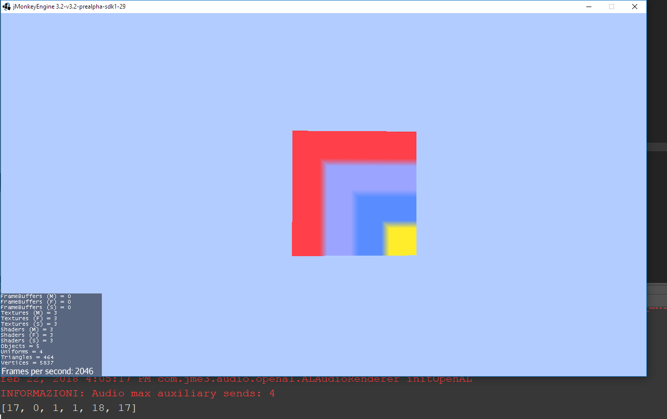
This is the problem (in the bottom of the screenshot you can see the indexes that make the triangles. The verteces are calculated by the cells, now only the left side of a single cell is being generated)
and the texture is this (I have used 0,0 - 1,0 - 1,1 - 0,1 as texture coordinates)
I have the whole mesh of a chunk and I have to apply multiple textures on it, teorically, but without knowing which texture coord on which vertex, it’s impossible even with a single texture
Either use different meshes for different textures or put your images into one texture atlas. That atlas will necessarily require you to use texture coordinate values that correspond to the part of the image you want to display.
Is there any reason you are writing all of this yourself instead of using something like the cubes framework that already exists? Seems like you might be in over your head and at least a working example would be helpful to you.
And note: if you thought “I’m going to make a block engine because those look easy…” Understand that block engines are actually the hardest to make. You get to use nothing “off the shelf” basically and will have to write everything (including a lot of physics, etc.) from scratch (unless you use someone else’s already existing library).
Edit: It generally also requires that you be a mesh/texture/shader expert and so on.
I have used the cubes framework, but it couldn’t generated the world dinamically. I mean: if I arrive at the end of the world it doesn’t generate a new piece of world. And on my computer it was quite slow in generating big worlds. I know block engines are hard to make, but I wanted to do this to challenge myself and I’m learning lots of new things while I make my engine bigger
But you didn’t tell me why the texture is applied that way on my mesh. So why does that happen?
The Indexes are in the screenshot, the texture coords are
0,0
1,0
1,1
0,1
I have different textures for every user-usable material so I create a geometry per chunk per ‘texture’. So grass has its own mesh, water has its own mesh, rock has its own mesh, etc… If I’d used a texture atlas then I could have done two meshes… one for all of the opaque textures and one for the transparent textures.
JME’s quad will show the whole texture because 0,0 is one corner of the texture and 1,1 is the other corner. If you want to show 1/4 of the texture then you pick a corner:
lower left: 0, 0 to 0.5, 0.5
lower right: 0.5, 0 to 1, 0.5
upper left: 0, 0.5 to 0.5, 1
upper right: 0.5, 0.5 to 1, 1
…at this point I’m just not sure what you are understanding. And “why does this look this way?” is only a useful question if I know all of the information. I don’t see the image you used or the code or anything.
“How long is this piece of red string I’m holding?”
I’ve resolved: having a Vector2f array to use in the texCoords buffer, the index of the vector2f storing a determined texture coords couple had to be the index in the vertices array corresponding to the texture points.
For Example, if the four vertices of my mesh are in indexes 0,17,18,301 of my vertices array, the texCoord code will be the following: