Ok, so maybe this is a really stupid question.
But I don’t understand what the line width is supposed to stand for.
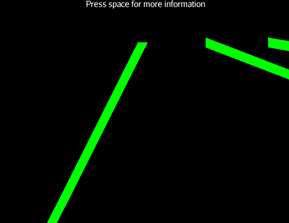
I was expecting something like line thickness but when I try it out, big values get me a stripe that switched between horizontal position and vertical position.
So I think I’m not getting what line width is, can anyone tell me please?
It’s measured in on-screen pixels, so if you make it 100 it will be a very thick and odd looking line.
Ok, but it’s not really thickness because I’m getting a weird stiff ribbon thing instead of a tube or a kind of cable.
Why is that?
post a screenshot or at least some code
Here it is:

Generated by:
[java]private void buildLine(Vector<Vector3f> pathPoints) {
Spline spline = new Spline(Spline.SplineType.CatmullRom, pathPoints, 0.5f, false);
Curve curve = new Curve(spline, 10);
curve.setLineWidth(20f);
Geometry pathGeo = new Geometry(“vehiclePath”, curve);
Material pathMat = new Material(assetManager, “Common/MatDefs/Misc/Unshaded.j3md”);
pathMat.setColor(“Color”, ColorRGBA.Green);
pathGeo.setMaterial(pathMat);
rootNode.attachChild(pathGeo);
}[/java]
It looks like it is drawing lines just fine at 20px, it could be your spline that is funky. Maybe try it in 2d (on the xz plane or something) and put some boxes at the path points to confirm that the spline is adhering to them.
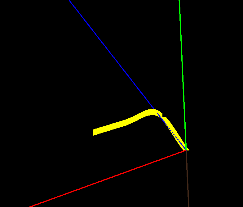
Here it is:

Those lines are the axis (but not scaled to one) so I think it’s safe to assume the spline is good.
I get the feeling that the curve is supposed to have those weird brakes at the middle. At the points where the angle is too sharp.
Well it looks to me as though the line is always drawing vertical or horizontal for the width rather than at the normal from the line…so at the point you cross the 45 degree mark it switches from horizontal to vertical and you get the discontinuity.
There may be a misunderstanding of what “line thickness” is. It is not a 3D value at all. It is factored in when the line is finally drawn on the screen. Not only is the distance in pixels but it’s just a raster effect causing an extra span of pixels to be drawn instead of just one pixel. Whether it’s above/below or left/right depends on the slope of the line… ie: the width is rendered in the axis that is not incremented by one during rasterization.
A line mesh is probably not really what you want in this particular use case.
Yeah a line has no dimension (or rather just one, it doesn’t exist in a 3d world), its just drawn so you can see it. You want tubes.
Because I was curious, I did a google for “openGL line joints” because I couldn’t remember if ogl had capping/joint support built in or not.
First hit:
OpenGL FAQ / 14 Rasterization and Operations on the Framebuffer
14.100 How do I turn on wide-line endpoint capping or mitering?
OpenGL draws wide lines by rendering multiple width-1 component lines adjacent to each other. If the wide line is Y major, the component lines are offset in X; if the wide line is X major, the component lines are offset in Y. This can produce ugly gaps at the junction of line segments and differences in apparent width depending on the line segment's slope.
OpenGL doesn't provide a mechanism to cleanly join lines that share common vertices nor to cleanly cap the endpoints.
One possible solution is to render smooth (antialiased) lines instead of normal aliased lines. To produce a clean junction, you need to draw lines with depth test disabled or the depth function set to GL_ALWAYS. See the question on rendering antialiased lines for more info.
Another solution is for the application to handle the capping and mitering. Instead of rendering lines, the application needs to render face-on polygons. The application will need to perform the necessary math to calculate the vertex locations to provide the desired capping and joining styles.
The last one is probably your best bet... ie: just generating your own mesh that has the width/3D characteristics that you want.
And just to put the last bullet in the dead horse…
To clarify what I was saying, I will use your own drawing with my hand-drawn illustration on top of it. 

The red line I’ve hand drawn represents the actual line as sent to rasterization. The yellow area is the lines extended up and then to the right of every pixel of the line in order to simulate thickness.
Thank you so much for all the input.
I really agree with @pspeed, I should probably generate my own mesh.
I have tons of questions about that but probably best to open a new topic on it (after I do some more research 8)).